SS7 for the
Common Man
Last modified: Sun, 05 Mar 2006 08:34:14 GMT
| Home |
| ||
| ||
| ||
| ||
| ||
| ||
OpenSwitch
Description: OpenSS7 Application Design Documentation.
A PDF version of this document is available here.
OpenSS7 VoIP Switch
OpenSS7 VoIP Switch
Executive Overview
This document provides a High-Level Design and Project Plan for the OpenSS7 VoIP Switch. The initial and primary purposes of this equipment is to provide a scalable, carrier-grade platform for interconnecting VoIP backbone networks to the PSTN using SS7.
The OpenSS7 Project
The OpenSS7 Project is an open source software project that has developed many protocol components within the SS7, SIGTRAN, ISDN and VoIP protocol stacks. Intellectual property rights for the OpenSS7 Project are held by OpenSS7 Corporation. All OpenSS7 Project software is eventually licensed under the GNU Affero General Public License. OpenSS7 Corporation also provide commercial licensing of OpenSS7 Project software under terms less restrictive than the AGPL.
The OpenSS7 VoIP Switch
OpenSS7 can provide VoIP gateway capabilities in a high-performance, low-cost, small-footprint platform leaveraging the GNU/Linux operating system distributions and tools, and utilizing low-cost commodity, or high-quality standardized hardware.
For details on platform applications, see Application Architecture, Network Architecture, Optional Application Support, and Optional Network Support.
Open Source Software
The OpenSS7 Project leverages the widespread use of GNU/Linux operation systems, distributions, and FSF tools such as ‘autoconf’ and RPM. For example, this document was formatted for PDF, HTML, info and plain text using the GNU texinfo system, ‘autoconf’, and the TeX formatting system.
The open source model avoids proprietary lock-in and permits in-house or outsourced development. All source code is available for use and modification by the end customer. All build tools, documentation and associated resources are generally available. The availability of the source code and complete documentation eases problem resolution and can offer upgrades and fixes even in advance of client problem reports.
For details on software solutions, see Protocol Architecture, Software Architecture, Optional Protocol Support, and Optional Software Support.
Commodity Hardware
By best utilizing commodity PC or standardized CompactPCI hardware, OpenSS7 makes available the highest performance platforms available on the market at back-to-school prices. When carrier-grade and large scale is not essential, 3GHz Pentium class servers in hardened rack mount chassis can be used at a fraction of the cost, and yet outperform, other solutions. Where carrier-grade is necessary, embedded Linux on standardized PICMG 2.16 NEBS compliant chassis make for a higher cost, but more reliable alternative.
For details on hardware solutions, see Platform Architecture, Hardware Architecture, and Optional Hardware Support.
Rapid Development
The OpenSS7 Project has already developed protocol components completing the SS7 and SIGTRAN signalling stacks including MTP Level 2 and Level 3, ISUP, SCCP, TCAP; and SCTP, M2PA, M2UA, M3UA, SUA and TUA. Development of a VoIP Switch to meet initial field requirements needs only the development of some intermediate and auxillary modules.
For details on scheduling, see Logistics.
An Evolving Solution
The OpenSS7 Project is evolving to support more protocol stacks including ISDN and VoIP. Support for an ever expanding capability is demonstrated by the additional options available as described in Optional Application Support, Optional Network Support, Optional Protocol Support, Optional Software Support, and Optional Hardware Support.
Conclusions
In summary, an OpenSS7 VoIP Switch an excellent application of the OpenSS7 SS7 and VoIP stacks and can be provided at a affordable price on short time-lines, while offering an evolution path for future deployment applications.
The OpenSS7 Project
Executive Summary
The overarching objective of this project is replacing Excel's existing Veraz Softswitches with an opensource replacement on rapid timelines in Excel's existing network. This is a high-risk development project with many development challenges that must be closely managed to be successful. The project is suitable for a time-boxing approach.
Under time-boxing, development gaps and deliverables are placed on a matrix with two axes which reflect increasing client need and increasing development effort. Then the deliverables which are most needed by the client and which require the least effort are attempted first, followed by lower needs and more effort, at last completed with the least need and the most effort.
While intended to be an iterative and refined process, the current time-boxing is as follows:
- Demonstrate M3UA interoperability with the Tekelec Eagle in a redundant configuration.
- Demonstrate interoperability with Excel's LNP LSCP (via the Tekelec Eagles using M3UA) by dipping the database for various numbers.
- Demonstrate interoperability with the Veraz, Cisco and Sonus Media Gateways1 by performing basic circuit connections, tone generation and detection using MEGACO/H.248 binary format over UDP per MSF per MSF-IA-MEGACO.003.01-FINAL.
- Demonstrate ISUP interoperability with the DMS-250 by performing Q.784/Telcordia interoperability testing. Perform call connections between DSM-250's utilizing a media gateway.
- Demonstrate ISUP to SIP and SIP to ISUP call handling via a Media Gateway.
- Demonstrate Application Server interaction (call-by-call control) and successful routing operation and billing generation.
- Demonstrate high-capacity call handling and redundant fail-over.
Preface
Document Information
Abstract
This document provides a High-Level Design and Project Plan for the OpenSS7 VoIP Switch.
Objective
The objective of this document is to provide a High-Level Design and Project Plan for the development of a low cost, high-performance, VoIP Switch using OpenSS7 SS7 stack components, software, and compatible systems and hardware.
Intent
The intent of this document is to act as a High-Level Design and Project Plan for a project for an OpenSS7 VoIP Switch. As a High-Level Design and Project Plan, this document discusses components and systems which are not necessarily complete. OpenSS7 Corporation is under no obligation to provide any software, system or feature listed herein.
Audience
This document is intended for a technical audience. The reader should be familiar with most ETSI, ITU-T and ANSI, Signalling System No. 7 recommendations, H.323, H.225, H.245, as well as IETF drafts and RFCS for RTP, SIP, SIP-T, MEGACO, MGCP, and SIGTRAN protocols.
Revisions
Take care that you are working with a current version of this document: you will not be notified of updates. To ensure that you are working with a current version, contact the Author, or check The OpenSS7 Project website for a current version.
ISO 9000 Compliance
Only the TeX, texinfo, or roff source for this document is controlled. An opaque (printed or postscript) version of this document is an UNCONTROLLED VERSION.
Disclaimer
OpenSS7 Corporation disclaims all warranties with regard to this documentation including all implied warranties of merchantability, fitness for a particular purpose, non-infringement, or title; that the contents of the document are suitable for any purpose, or that the implementation of such contents will not infringe on any third party patents, copyrights, trademarks or other rights.. In no event shall OpenSS7 Corporation be liable for any direct, indirect, special or consequential damages or any damages whatsoever resulting from loss of use, data or profits, whether in an action of contract, negligence or other tortious action, arising out of or in connection with any use of this document or the performance or implementation of the contents thereof.
OpenSS7 Corporation reserves the right to revise this software and documentation for any reason, including but not limited to, conformity with standards promulgated by various agencies, utilization of advances in the state of the technical arts, or the reflection of changes in the design of any techniques, or procedures embodied, described, or referred to herein. OpenSS7 Corporation is under no obligation to provide any feature listed herein.
Document Organization
This document is organized as follows:
1 Introduction
This document provides a High-Level Design and Project Plan for a platform to provide scalable OpenSS7 VoIP Switch capabilities. The primary driver for the OpenSS7 VoIP Switch is to provide a system capable of interconnecting a VoIP backbone to the PSTN using SS7. This document provide a high-level design and proposal for a production system to provide this capability at a number of scale points.
The proposal utilizes, where possible, existing OpenSS7 SS7, SIGTRAN and VoIP stack components and provides a development plan for components that are specific to the OpenSS7 VoIP Switch initial requirements.
This document discusses the resulting software configuration that will be put in place on the production system, the platform configuration for the production system, and a network configuration for deployment. Also discussed is an overview of the project management logistics for successful completion over the course of this development project.
It is intended that the document be a “living” document, that is updated over the course of this development project.
1.1 The OpenSS7 VoIP Switch
This project provides an OpenSS7 VoIP Switch platform that provides interconnection to the PSTN using SS7 ISUP trunks and is capable of routing calls to and from the PSTN and a VoIP backbone network using SIP, SIP-T, H.323 or BICC signalling and controlling Media Gateways utilizing RTP transport using MEGACO/H.248.
1.2 Project Drivers
The lead purpose of the OpenSS7 VoIP Switch is to provide PTSN interconnection to an existing VoIP backbone and deployment infrastructure using a fully opensource solution.
1.3 Scope
Because of early deployment drivers, requirements for scale, yet a focus on opensource software, the OpenSS7 VoIP Switch platform is constructed using standardized COTS (Commodity Off The Shelf) hardware in a NEBS 3/ETSI compatible chassis providing cost effective servicability and reliability. Carrier-grade serviciability and reliability utilizing standardized PICMG 2.16 or AdvancedTCA telephony hardware in a a NEBS 3/ETSI compliant chassis for more hardenned installations remains possible.
1.3.1 Objectives and Milestones
The project lays out the following objectives, in no particular order:
- Establish interoperability with the Veraz Media Gateway. It is intended that the Veraz Media Gateway be controlled using MEGACO/H.248 Version 2 binary format over UDP or SCTP per MSF-IA-MEGACO.003.01-FINAL. Successful interoperability will be demonstrated by successfully connecting basic calls at the local and access tandem level on SS7 IMTs.
- Establish interoperability with the Cisco Gateway. It is intended that the Cisco Media Gateway be controlled using MEGACO/H.248 Version 2 binary format over UDP or SCTP per MSF-IA-MEGACO.003.01-FINAL. Successful interoperability will be demonstrated by successfully connecting basic calls at the local and access tandem level on SS7 IMTs.
- Establish interoperability with the Sonus Media Gateway. It is intended that the Sonus Media Gateway be controlled using MEGACO/H.248 Version 2 binary format over UDP or SCTP per MSF-IA-MEGACO.003.01-FINAL. Successful interoperability will be demonstrated by successfully connecting basic calls at the local and access tandem level on SS7 IMTs.
- Establish interoperability with the Tekelec Eagle M3UA implementation. It is intended that the Tekelec Eagle be interconnected using RFC 3332, RFC 4666 or ETSI TS 102 142 M3UA using RFC 2960, RFC 4460 or ETSI TS 102 141 SCTP. Successful interoperability will be demonstrated by successfully exchanging ISUP and LNP/TCAP signalling via the STP.
- Establish interoperability with a DMS-250. It is intended that the DMS-250 be interconnected using ANSI ISUP. Sucessful interoperability will be demonstrated by successfully connecting basic calls at the local and access tandem level on SS7 IMTs.
- Establish interoperability with an (unidentified vendor) LNP LSCP. It is intended that the LSCTP be interconnected using ANSI TCAP. Successful interoperablity will be demonstrated by successfully dipping the LNP database.
- Establish interoperatbiliy with an Application Server peforming call-by-call control, the design and
implementation to be provided by Excel.
It is currently intended that SPIRITS or INAP or AIN be used by the Application Server (SCP) to
control the OpenSS7 VoIP Switch running an AIN/INAP call model.
Successful interoperability will be demonstrated by successfully connecting basic calls at the local
and access tandem level on SS7 IMTs, including:
- Connect ISUP to ISUP calls across Excel's network.
- Connect ISUP to SIP calls across Excel's network.
- Connect SIP to ISUP calls across Excel's network.
- Connect SIP to SIP calls across Excel's network.
- Demonstrate high levels of call handling capability (over 250 calls per second) in the laboratory.
- Demonstrate high levels of call handling capability under failover scenarios in the laboratory.
1.3.2 Phases and Timeboxing
The longer term project is broken into the following phases:
- Phase 1 2
- The initial phase of the project is intended to provide the capabilities of the OpenSS7 VoIP Switch
for PSTN to VoIP backbone tandem for H.323.
- Phase 2
- The second phase of the project adds tandem gateway capabilities for SIP-T.
- Phase 3
- The third phase of the project adds network service capabilities.
- Phase 4
- The fourth phase of the project adds softswitch capabilities.
- Phase 5
- The fifth phase of the project completes a VoIP (NGN) switch.
Although some reference is made to capabilities supporting other phases, Phase 1 and Phase 2 are the focus of this document.
1.3.3 Gates
Each phase of the project consists of seven gates. The seven gates are defined as follows:
- Gate 0 — Concept
-
Gate 0 is passed when the initial concept has been elucidated and work is begun on a
High-Level Design. This is an internal OpenSS7 gate.
- Gate 1 — High-Level Design
-
Gate 1 is passed when the high-level design has been reviewed to the satisfaction of the
consumers of the project. This is an external review gate. OpenSS7 internally passes this gate
once the High-Level Design has been published and work is begun on a detailed design.
3
- Gate 2 — Detailed Design
-
Gate 2 is passed when the detailed design has been reviewed to the satisfaction of the
consumers of the project and the developers on the project. This is an external as well as an
internal review gate. OpenSS7 passes this gate once the Detailed Design has been published and work
base begin on development and implementation of the design.
4
Passing this gate moves from the design stage to the development stage of the project.
- Gate 3 — Development and Implementation
-
Gate 3 is passed when the software and systems development and implementation to the detailed
design is complete and testing has begun. This is an internal review gate. OpenSS7 internally
passes this gate when software is code complete and hardware has been installed for testing.
- Gate 4 — System Test
-
Gate 4 is passed once the product implementation meets all internal ad hoc and formal
conformance test suites and internal testing is complete. This is an internal review gate. OpenSS7
passes this gate internally once conformance testing is complete. Passing this gate moves from the
development stage to the support stage of the project.
- Gate 5 — Acceptance Test
-
Gate 5 is passed once the product implementation has passed external Gamma client acceptance
testing. This is an external review gate. OpenSS7 passes this gate internally once participation
in external acceptance testing is complete.
- Gate 6 — Project Complete
- Gate 6 is passed once all support obligations for the product implementation have been discharged. This is an internal review gate. OpenSS7 passes this gate once support agreements have terminated.
For more details on Gate scheduling for Phase 1 and Phase 2 of the VoIP Switch project, see Schedule.
2 Application Architecture
The OpenSS7 VoIP Switch is intended to provide high performance and high density PSTN to VoIP backbone gateway adding SS7 interconnection capability to an existing or back-end VoIP network.
2.1 Application Requirements
Application requirements have been broken into 5 phases using the timeboxing approach.
2.1.1 Phase 1 Requirements
Phase 1 requirements provide a VoIP gateway capability that will connect an existing H.323 VoIP network to the PSTN using SS7 ISUP trunks.
- Integral Media Gateway for RTP/RTCP to G.703/G.704 G.711 A- and mu-law.
- Integral Signalling Gateway for SS7 ISUP and SS7 TCAP.
- Local Number Portability.
- Lawful Intercept.
- Integral Media Gateway Controller for H.323
- Integral Back End functions for H.323.
- Integral H.323 Gatekeeper.
2.1.2 Phase 2 Requirements
Phase 2 requirements provide SIP-T capabilities.
- Integral Media Gateway Controller for SIP-T.
- Integral Back End functions for SIP-T.
- Integral SIP redirect/proxy server.
2.1.3 Phase 3 Requirements
Phase 3 requirements provide network service capabilities.
- ENUM support.
- AAA support.
- EAP authentication.
- External PLMN authentication.
- GSM MSC/VLR capabilities.
- ETSI Tiphon 4 interworking.
- ISDN support on E interface.
2.1.4 Phase 4 Requirements
Phase 4 requirements expose internal interfaces to provide softswitch capabilities.
- J Interface (SIGTRAN) exposed.
- N Interface (MGCP, H.248/MEGACO) exposed.
2.1.5 Phase 5 Requirements
Phase 5 requirements complete full VoIP (NGN) switching.
- Support for directly attached H.323, SIP and MGCP IP Phone terminals.
- Full RAS support for internal H.323 gatekeeper and SIP proxy server.
- Full class 5 residential/business feature set.
2.2 Solution Architecture
Although the functions of Media Gateway Controller, Media Gateway and Signalling Gateway have been decomposed, and in the past these functional groups have been implemented on separate physical platforms, modern compute capacity and densities permit these functions to be integrated into a single phyical platform without limitation. Open standard interfaces are utilized internal to the platform to permit a decomposed model to be split out and to permit ETSI Tiphon Version 4 compatibility.
2.2.1 OpenSS7 VoIP Switch for Deployment
In light of the foregoing, the solution architecture takes the form of an integrated VoIP switch capability of providing a number of functional groups in the traditional models. The OpenSS7 VoIP Switch integrates the following functional groups while still permitting standard interfaces to be exposed for maximum deployment flexibility:
- Integral Media Gateway Controller for H.323 and SIP-T.
- Integral Media Gateway for RTP/RTCP to PDH G.703/704 G.711 conversion.
- Integral Signalling Gateway for SS7 ISUP, TCAP and ISDN signalling conversion.
- Integral Gatekeeper for H.323 and redirect/proxy server for SIP-T.
2.3 Call Flows
This section provides some illustrative application call flows:5
3 Network Architecture
Figure 1 illustrates the network configuration for the OpenSS7 VoIP Switch in a deployment scenario. The gateway device is positioned and attached to the SS7 network (PSTN) and the IP network (VoIP).
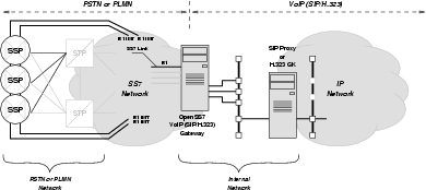
The VoIP Switch device is positioned between the SS7 network and the IP network providing VoIP communications.
The device is attached to the telephone network with two-way SS7 Inter Machine Trunks (IMTs) and SS7 signalling links. SS7 signalling links may be either A-links to STPs in the SS7 network, or F-links directly to interconnect SS7 switching offices within the telephone network. SSPs within the telephone network to which the devices is interconnected would have to be configured to deliver calls for the device to SS7 ISUP trunks interconnected to the device. For the purposes of the telephone network, the VoIP Switch would appear as a National intermediate office, but could also act as an International intermediate office or International incoming or outgoing office. Configuration as a National originating or terminating office is also possible. Full continuity testing, blocking and management of ISUP circuits is provided for by the OpenSS7 ISUP protocol module.
The device is attached to the SS7 utilizing CPC-388 or lesser grade OpenSS7 SS7 link and media channel TDM interface cards, 6 terminating SS7 A-links or F-links, either 64kbps Q.703 links or full span Q.703 Annex B 2.048Mbps high-speed links, or via a signalling gateway device terminating SS7 Level 2, 3 or 4 and transporting M2UA or M3UA back-haul signalling to the gateway device over SCTP. The device is configured to perform routing of calls incoming from the telephone network based on ENUM lookups and INAP/SPIRITS triggers to RTP streams controlled by SIP or H.323 within the OpenSS7 complex. 7 The device is also responsible for switching and converting 64kbps digital paths from the IMTs terminated on the telephone network side to RTP media streams (using any encoding) on the OpenSS7 complex side. Full interworking of echo suppression/silence detection/comfort tone between ISUP and RTP will be performed. This switching is performed using the OpenSS7 internal Media Switch (MG) switching which provides for non-blocking switching of voice channels across TE410, CPC 384 or CPC 388 devices in the platform, as well as switching and conversion between RTP streams on dual Ethernet rails. On the OpenSS7 complex side of the device, calls are connected to RTP streams on attached Ethernet and routed using the Client IP network. The VoIP Switch will act as a SIP proxy and H.323 Gatekeeper querying on-board or off-board ENUM DNS servers, and performing SIP/H.323 signalling to clients or other proxy/gatekeepers across the IP network. It could also be capable of INAP SSP/IP operation as well as a SPIRITS.
Calls outgoing from the OpenSS7 complex to the telephone network will be directed on the basis of subscription or by proxy/gatekeeper origination to the interconnected IMT trunks with or without number analysis.
Existing equipment may also be attached with ISDN PRI connections directly to the VoIP switch with the device acting in Network mode. This permits local PBX to be attached using ISDN. The VoIP switch would also be capable of BICC switching between VoIP switches as well as M2UA/M3UA distribution of signalling links and signalling points to permit a distributed and fully redundant IP architecture.
The telephone network side of the device signals using an ETSI ISUP Version 2 compliant National variant to the local interconnect controlling E1 facilities. The OpenSS7 side of the device signals using SIP-T or H.323 directly to SIP proxies or H.323 GK and terminal devices within the IP network. The device is also responsible for switching E1 voice channels into RTP streams.
The purpose of the VoIP Switch device is to provide SS7 ISUP access directly into the OpenSS7 VoIP environment, without the need for additional expensive or proprietary equipment.
On the VoIP network side of the device, the platform is connected on an internal LAN with multiple Ethernet segments and IP subnetworks through a Layer 2 switch to VoIP backbone routers. SIP calls originating within the VoIP network are accepted and responded to by the VoIP Switch application. Outgoing calls are tandemed to the PSTN over SS7 ISUP signalling and circuits. RTP channels are terminated on the gateway device and converted to 64kbps A-law ISUP TDM circuits.
From the viewpoint of the SS7 network, the gateway device acts as an SS7 SSP intermediate or originating/terminating switch with its own SS7 signalling point code. From the viewpoint of the VoIP network, the gateway device acts as SIP or H.323 gateway, or a BICC intermediate switch.
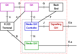
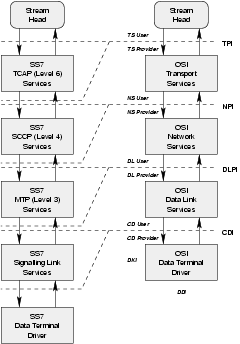
4 Reference Architecture
Figure 2 illustrates the VoIP Switch reference interfaces form the ETSI Tiphon model.
4.1 VoIP Switch Reference Entities
The following functional entities are used to decompose functions in the VoIP switch and network:
4.1.1 Terminal
The H.323 or SIP terminal support the A or B interface. The A interface is used for communicating with H.323 Gatekeepers or other H.323 Terminals, or SIP FS, PS or UAC.
Terminal devices are extenal to the VoIP Switch. In initial phases, terminal device interface (see see Reference Interface A) will only be supported via external H.323 Gatekeepers, SIP forwarding servers or SIP proxy servers. Terminal device attachment for H.323, SIP and H.248 terminals will be supported in later phases.
4.1.1.1 H.323 Terminal
4.1.1.2 SIP Terminal
4.1.1.3 H.248/MEGACO Terminal
4.1.2 Gatekeeper
The H.323 Gatekeeper, SIP forwarding server, or SIP proxy server, supports the A, C, D and G interfaces.
The VoIP Switch will support an internal Gatekeeper function that will initially support the D interface, and support the A interface in later phases. Initially the G and F interfaces will be internal to the platform, and will be exposed in later phases.
4.1.3 Media Gateway Controller
The H.323 or SIP Media Gateway Controller supports the C, F, J and N interfaces.
The VoIP Switch will incorporate an integral Media Gateway Controller function. In initial phases, the C, F, J and N interfaces will be internal to the platform. In subsequent phases, these interfaces will be exposed.
4.1.3.1 H.323 MGC
4.1.3.2 SIP MGC
The SIP Media Gateway Controller is primarily responsible for conversion of SCN signalling from the PSTN on the J Interface to VoIP signalling to the H.323 Gatekeeper or SIP redirect/proxy server on the C Interface. Also, the SIP MGC must coordinate this conversion with the control of media conversion from G.703/704 G.711 A- and mu-law circuits from the PSTN to RTP/RTCP channels within the VoIP network.
Conversion between SS7 ISUP signalling and SIP-T signalling is described in
4.1.4 Media Gateway
The Media Gateway supports the N and B interfaces.
The VoIP Switch will incorporate an integral Media Gateway function. In initial phases, the N interface will be internal to the platform. In subsequent phases, the N interface will be exposed.
The current document is concerned with media gateway functionality for media gateways supporting SS7 ISUP trunks (G.703/704) and ISDN PRI trunks (G.703/704).
4.1.5 Signalling Gateway
The Signalling Gateway supports the J and E.b interfaces.
The VoIP Switch will incorporate an integral Signalling Gateway function. In initial phases, the J interface will be internal to the platform. In subsequent phases, the J interface will be exposed.
The current document is concerned with signalling gateway functionality for SS7 ISUP, SS7 TCAP, and ISDN Q.931/921 signalling.
4.1.6 Back End
The back end supports the F and G interfaces.
The VoIP switch will incorporate an integral Back End function. In initial phases, the F and G interfaces will be internal to the platform. In subsequent phases, the F and G interfaces will be exposed.
The current document is concerned about operational support systems, bulling systems, and service menagement systems. I addition, database services (AIN/SPIRITS/etc) are considerered at this interface.
4.2 VoIP Switch Reference Interfaces
4.2.1 Reference Interface A
This is the interface of the H.323 Terminal or SIP Terminal to the H.323 Gate Keeper or SIP Proxy.
Figure 3 illustrates the protocols at the A Interface.
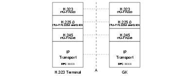
4.2.1.1 Interface A — H.323
Figure 3a illustrates the use of H.323 based protocols at the A Interface.

Protocols at this interface for H.323 operation include:
- H.323
- H.225.0
- Q.931
- H.245
- TCP
- SCTP
4.2.1.2 Interface A — SIP
Figure 3b illustrates the use of SIP based protocols at the A Interface.
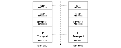
Protocols at this interface for SIP operation include:
- SIP (UAC–UAS)
- SDP
- HTTP/1.1
- TCP
- SCTP
In initial phases of the VoIP Switch project, the A interface will not be directly supported. The A Interface will be suppored in later phases of the project.
4.2.2 Reference Interface B
This is the interface of the Terminal to the Media Gateway.
Protocols at this interface include:
- RTP/RTCP
- UDP
- IP
4.2.3 Reference Interface C
This is the interface of the Media Gateway Controller to the H.323 Gate Keeper or SIP Proxy.
Figure 5 illustrates the protocols at the C Interface.
In initial phases of the VoIP Switch project, the C interface will be internal to the platform. The C Interface will be exposed in later phases of the project.
4.2.3.1 Interface C — H.323
Figure 5a illustrates the protocols supporting H.323 at the C Interface.

Protocols at this interface for H.323 operation include:
- H.323
- H.225.0
- Q.931
- H.245
- TCP
- SCTP
4.2.3.2 Interface C — SIP
Figure 5b illustrates the protocols supporting SIP-T at the C Interface.

Protocols at this interface for SIP operation include:
- SIP (SIP-T)
- SDP (ISUP)
- HTTP/1.1
- TCP
- SCTP
4.2.3.3 Interface C — BICC
Protocols at this interface for BICC operation include:
- BICC
- TCP
- SCTP
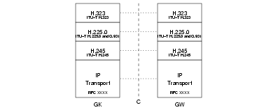
4.2.4 Reference Interface D
This is the interface of the H.323 Gate Keeper or SIP Proxy to the H.323 Gate Keeper or SIP Proxy.
Figure 6 illustrates the protocols at the D Interface.
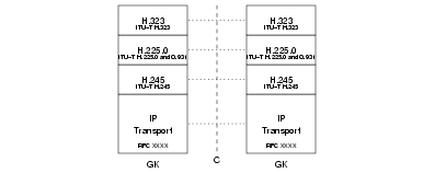
4.2.4.1 Interface D — H.323
Figure 6a illustrates the protocols supporting H.323 at the D Interface.

Protocols at this interface for H.323 operation include:
- H.323
- H.225.0
- H.245
- TCP
- SCTP
4.2.4.2 Interface D — SIP
Figure 6b illustrates the protocols supporting SIPT at the D Interface.

Protocols at this interface for SIP operation include:
- SIP (SIP-T)
- SDP
- HTTP/1.1
- TCP
- SCTP
4.2.4.3 Interface D — BICC
Protocols at this interface for BICC operation include:
- BICC
- TCP
- SCTP
4.2.5 Reference Interface E
This is the interface of the Gateway to the Switched Circuit Network. It consists of two interfaces: a signalling interfaces (E.b) and a circuit interface (E.a).
4.2.5.1 Reference Interface E.a
This is the circuit interface from the gateway to the switched circuit network.
Interface E.a — ATM
Protocols at this interface for ATM operation include:
- ATM AAL2
- ATM AAL3
Interface E.a — PDH
Protocols at this interface for PDH operation include:
- G.703
- G.704
4.2.5.2 Reference Interface E.b
This is the signalling interface from the gateway to the switched circuit network.
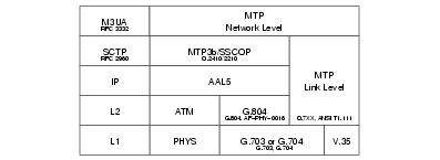
Interface E.b — SS7
Figure 8a illustrates protocols in support of SS7 signalling at the E.b Interface.

Protocols at this interface for SS7 operation include:
- TCAP
- SCCP
- ISUP
- SS7-MTP
Interface E.b — ISDN
illustrates protocols in support of ISDN signalling at the E.b Interface.
Protocols at this interface for ISDN operation include:
- ISDN Q.931
- ISDN Q.921
Interface E.b — ATM
Figure 8c illustrates protocols in support of ATM signalling at the E.b Interface.
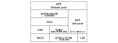
Protocols at this interface for ATM operation include:
- B-ISUP
- MTP3b
- SSCOP
- AAL5
4.2.6 Reference Interface F
This is the interface of the Media Gateway Controller to Back End OSS.
Protocols at this interface include:
- ENUM
- SPIRITS
- AAA
4.2.7 Reference Interface G
This is the interface of the H.323 Gatekeeper or SIP Proxy to the back end OSS.
Protocols at this interface include:
- ENUM
- SPIRITS
- AAA
In initial phases of the VoIP Switch, the G Interface will be internal to the platform. The G Interface will be exposed in later phases.
4.2.8 Reference Interface J
This is the interface of the Media Gateway Controller to the Signalling Gateway.
Figure 11 illustrates the protocols at the J Interface.

In initial phases of the VoIP Switch, the J interafe will be internal to the platform. The J Interface will be exposed in later phases.
4.2.8.1 Interface J – SS7
Figure 11a illustrates the protocols in support of SS7 signalling at the J Interface.

Protocols at this interface for SS7 operation include:
- TUA
- SUA
- ISUA
- M3UA
- M2UA
- M2PA
- SCTP
- TALI
- TCP
4.2.8.2 Interface J – ISDN
Figure 11b illustrates the protocols in support of ISDN signalling at the J Interface.

Protocols at this interface for ISDN operation include:
- IUA
- DUA
- SCTP
4.2.8.3 Interface J – GR303/V5.2
Figure 11c illustrates the protocols in support of GR303/V5.2 signalling at the J Interface.

Protocols at this interface for GR303/V5.2 operation include:
- V5UA
- GR303UA
- SCTP
4.2.9 Reference Interface N
This is the interface of the Media Gateway Controller to the Media Gateway.
Protocols at this interface include:
- MGCP
- H.248/MEGACO
- TCP
- SCTP
In initial phases of the VoIP Switch, the N interface will be internal to the platform. The N Interface will be exposed in later phases.
5 Protocol Architecture
illustrates the protocol configuration for the OpenSS7 VoIP Switch system. The protocol stack uses the following OpenSS7 stack components:
The following Protocol Stacks are provided as part of the OpenSS7 SS7 and VoIP stacks:
5.1 Applications
5.1.1 OpenSwitch Call Framework Application
The OpenSwitch Call Framework Application uses the OpenSwitch C++ call framework supporting Call Control Interface (CCI) based called control, Media Gateway Interface (MGI) based media switching and conversion, and Transaction Component Interface (TCI) based transactions. This is the module that performs call control, transaction services, and media switching conversion. This component is also responsible for triggers, digit translations, call and feature usage record generation, operational measurements, call and feature statistics and maintenance. To perform its functions it interfaces with ISUP, ISDN, BICC, SIP and H.323 signalling stacks using the published Call Control Interface (CCI), interfaces with the Media Gateway (MG) switching and conversion control stack using the published Media Gateway Interface (MGI), and interfaces with the transaction engine using the published Transaction Component Interface (TCI). Because the CCI, MGI and TCI are largely independent of the protocol stack providing call control signalling, the protocol stack providing media switchingconversion services, and the protocol stack providing transaction services, the OpenSwitch Call Framework application can be migrated to other ISUP and ISDN related protocols (e.g. BSSAP) and to other MG control protocols (e.g. MGCP or H.248) without significant impact on the OpenSwitch Call Framework.
5.2 SS7 Stack
SS7 stack components provide support for protocols in the protocol profile at the E.b Interface (see Reference Interface E.b). They provide Signalling Gateway (SG) function within the OpenSS7 VoIP Switch for support of SS7 SIGTRAN protocols at the J Interface, (see Reference Interface J). 8
5.2.1 ISUP/BICC/ISDN Operations Maintenance and Administration
The ISUP/BICC/ISDN OAM&P module is responsible for configuration of the SS7 and ISDN stacks, maintenance, statistics collection, operational measurements, management events and controls, log and alarm generation. This is a daemon process that is typically customized to meet a specific application.
5.2.2 Integrated Services Digital Network (ISDN) User Part (ISUP)
The ISUP driver performs the call functions necessary for switching calls under ISUP control. The driver is capable of acting in originating, intermediate and terminating switching roles in both the National and International networks. The driver provides interface to the OpenSwitch Call Framework application using the OpenSS7 Call Control Interface (CCI). This is the same interface that is used by the BICC, ISDN, SIP and H.323 drivers as well as OpenSS7 BSSAP, V5.2 and GR303 drivers.
The ISUP drvier supports all CCITT/ITU-T version (Blue Book forward), ETSI and ANSI versions (1992 forward), including circuit management. The ISUP driver provides a specialized Call Control Interface (CCI) to its users and accepts an Message Transfer Part Interface (MTPI) from below.
The ISUP driver is a STREAMS driver that runs in the Linux Kernel for maximum performance. The primary scale limiting characteristics of the ISUP drvier is the number of simultaneous calls and the rate of call attempts. Each simultaenous call requires state information and dynamic call information. Call identifier indexed hash tables must be appropriately sized and the mean and maximum simultaneous calls should be known for proper sizing.
The Integrated Services Digital Network (ISDN) User Part (ISUP) STREAMS driver is responsible for providing ISUP services on top of a Message Transfer Part (MTP) or MTP Level 3 User Adaptation Layer (M3UA) stream.
The OpenSS7 ISUP module supports all ISUP functions with the exception of performing actions on the bearer circuits. Actions on the bearer circuits are expected to be performed by the ISUP User utilizing the Media Gateway (MG) stack components.
Message Transfer Part (MTP) streams as linked beneath the ISUP module to provide MTP services to ISUP. Alternately, a SIGTRAN MTP Level 3 User Adatapation Layer (M3UA) or OpenSS7 STREAMS over SCTP stream may be linked.
The OpenSS7 ISUP driver contains all the necessary state machines, timers, circuit management and error handling as required by the ITU-T, ETSI and ANSI specifications.
This is an existing OpenSS7 SS7 stack component; for documentation, see: isup(4).
5.2.3 Transaction Capabilities Application Part (TCAP) Driver
The transaction capabilities application part driver performs the essential transaction functions of the SS7 signalling stack. SCCP or SUA streams are linked under the driver and the driver provides the functions of a TCAP SSP or SCP, MSC or HLR, SMSC and other TCAP nodes. Transaction Capabilities Application Part streams bound to INAP, MAP or LNP TCAP-SAPs are accessed by the transaction application using the Transaction Component Interface (TCI).

The TCAP driver supports all CCITT/ITU-T versions (Blue Book forward), ETSI and ANSI versions (1992 forward), including operation classes 1 through 5. The TCAP driver provides a specialized TR and TC interface to its users and accepts an X/Open NPI Revision 2.0 interface from beneath. In addition, a TPI Revision 2.0 user interface supporting an X/Open XNS 5.2 mOSI XTI library interface is provided.
The TCAP driver is a STREAMS driver that runs in the Linux kernel for maximum performance. The primary scale limiting characteristic of the TCAP driver is the number of simultaneous open transactions. Each open transaction requires a number of timers, state information and dynamic transaction information such as addressing. Transaction Identifier indexed hash tables must be appropriately sized and the mean and maximum simultaneous open transactions should be known for proper sizing.
The Transaction Capabilities Application Part (TCAP) STREAMS module is responsible for providing TCAP services on top of a Signalling Connection Control Part (SCCP) or SCCP-User Adaptation Layer (SUA) stream. In addition, it is possible to use an ISO/OSI Network Service Provider to provide the network services to TCAP.
The OpenSS7 TCAP component has message encoding and decoding for ITU-T/ETSI Application Context TCAP and ANSI Private TCAP. Interfaces provided to TCAP users include an XTI/mOSI capable TPI Version 2.0 interface, a Transaction Interface (TRI) as described in ITU-T Q.791, and a Component Interface (TCI) as also described in ITU-T Q.791. The ITU-T Q.791 TR and TC interfaces are support Java JTCAP.
Of these interfaces, the Transaction Interface (TRI) and Component Interface (TCI) are most efficient. This is because it is not necessary to open a new stream for each transaction as is the case with the TPI interface and the XTI/mOSI.
The OpenSS7 TCAP module supports all Operations Classes.
A SIGTRAN TCAP-User Adaptation Layer (TUA) or OpenSS7 STREAMS over SCTP multiplexing driver can be used between the TCAP and the TCAP-User to export the TCAP/TCAP-User interface between a provider and user host.
Signalling Connection Control Part (SCCP) streams are linked beneath the TCAP module to provide SCCP services to TCAP. Alternately, a SIGTRAN SCCP-User Adaptation Layer (SUA) or OpenSS7 STREAMS over SCTP stream may be linked.
The OpenSS7 TCAP module contains all the necessary state machines, timers, transaction error handling and component error handling as required by the ITU-T, ETSI and ANSI specifications.
This is an existing OpenSS7 SS7 stack component; for documentation, see: tcap(4).
5.2.4 Signalling Connection Control Part (SCCP) Driver
The signalling connection control part driver performs the essential transport functions of the SS7 signalling stack. Message Transfer Part or MTP3 User Adaptation Layer streams are linked under the driver and the driver provides the functions of a SCCP endpoint or relay with full global title translations. Signalling Connection Control Part streams bound to TCAP SCCP-SAPs are linked under the TCAP driver to form a complete SS7 stack in support of call transactions.
The SCCP driver supports all CCITT/ITU-T versions (Blue Book forward), ETSI and ANSI versions (1992 forward), including both connectionless and connection-oriented protocol classes 0 through 3. The SCCP driver provides an extended NPI Revision 2.0 interface to its users and accepts an NPI Version 2.0 (Connectionless) MTP interface from beneath or a specialized OpenSS7 MTPI interface. In addition, a TPI Revision 2.0 user interface supporting an X/Open XNS 5.2 XTI library interface is provided.
The SCCP driver also provide GTT streams for servicing Global Title Translations requests. These streams can be used by a user-space program for servicing GTT requests from a local or remote database, or can have specialized STREAMS modules pushed to perform rule-based GTT in the operating system kernel.
The SCCP driver is a STREAMS driver that runs in the Linux kernel for maximum performance.
The Signalling Connection Control Part (SCCP) STREAMS module is responsible for providing SCCP services on top of a Message Transfer Part (MTP) Level 3 (MTP3) or MTP3-User Adaptation Layer (M3UA) stream. In addition, it is possible to use an ISO/OSI connectionless Network Service Provider to provide the network services to SCCP.
The OpenSS7 SCCP component has message encoding and decoding for ITU-T/ETSI and ANSI SCCP. Interfaces provided to SCCP users include an XTI/OSI capable TPI Revision 2.0 interface, an NPI Revision 2.0 interface, and an SCCP-specific interface.
The OpenSS7 SCCP module supports all Protocol Classes.
This is an existing OpenSS7 SS7 stack component; for documentation, see: sccp(4).
5.2.5 Global Title Translations (GTT)
The Signalling Connection Control Part (SCCP) Global Title Translations (GTT) module is responsible for responding to SCCP-GTT translations originating from the SCCP module beneath and is responsible for generating outgoing SCCP-GTT translations to the SCCP module beneath. To perform its function, the SCCP-GTT indexes all information based on the SCCP Address, including dynamic (state) and provisioned (result) information. For performance in both a testing and production environment, the module provides three levels of database partitioning and caching:
- Rules
- Rules can be provided that are used to determine provisioned information based on components of
the index (GT). These rules can be used to generate a rather large simulated database without
maintaining or accessing large database record areas. The rule base provides a simulated
partitioned database. Each rule refers to a template or partial template of provisioned data.
- Templates
- Templates can be provided that specify a profile of provisioned information for a class of
indexes (GT). Templates provide a compact local in-kernel cache of templates. Indexes reference
templates rather than complete records.
- Records
- Records can be provided that specify the provisioned information for the specific index (GT).
Records provide a local in-kernel cache of specified records. Records are unique for each index.
- Translations
- The application can be queried by indicating the index (GT) and the module awaits a response
containing the provisioned information. Translations provide access to an external database or
algorithm.
For the OpenSS7 VoIP Switch, messages can be routed on Translation Type or on the basis of the Subsystem Number alone, resulting in a simple rule provided to the SCCP-GTT. If the OpenSS7 VoIP Switch application is not expected to perform in any other role, the OpenSS7 VoIP Switch application can bind as the "Default Destination" for all SCCP Unitdata messages, obviating the need for GTT.
This is an existing OpenSS7 SS7 stack component; for documentation, see: sccp(4).
5.2.6 Message Transfer Part (MTP)
The message transfer part driver performs the essential network functions of the SS7 signalling stack. Signalling link streams (see below) are linked under the driver and the driver provides the functions of a Signalling End Point (SEP) or Signalling Transfer Point (STP).
Message Transfer Part streams bound to ISUP MTP-SAPs are linked under the ISUP driver above to form a complete SS7 stack in support of call switching. 9
The MTP driver supports all CCITT/ITU-T versions (Blue Book forward), ETSI and ANSI versions (1992 forward), including full transfer function. The MTP driver provides a specialized MTP interface to its users, in addition to an NPI Revision 2.0 connectionless interface. A TPI Revision 2.0 (connectionless) user interface support X/Open XNS 5.2 XTI library functions is also provided.
The MTP driver is a STREAMS driver that runs in the Linux kernel for maximum performance.
The Message Transfer Part (MTP) Level 3 (MTP3) module is responsible for providing MTP services to its users.
The Message Transfer Part (MTP) Level 2 (MTP2) module is responsible for providing MTP services to its users.
These are an existing OpenSS7 SS7 stack components; for documentation, see: mtp(4).
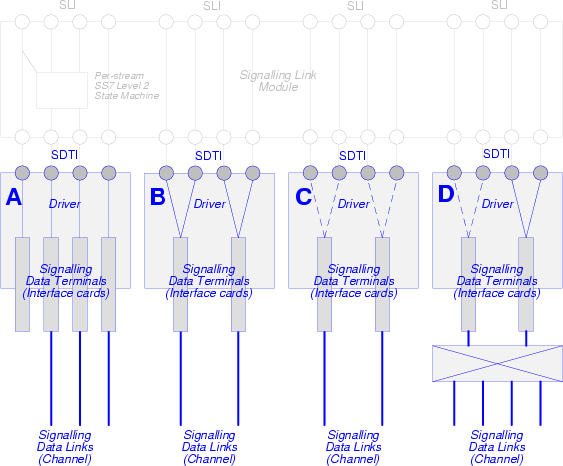
5.2.7 Signalling Link (SL) Module
The signalling link module performs HDLC and SS7 Message Transfer Part Level 2 (Link) functions on a raw communications channel provided by the X400P driver and the E400P card. This module converts between the channel media stream (raw octet stream) and an SS7 signalling link signalling stream. These streams comprise SS7 signalling links and are linked under the MTP driver.
The signalling link module performs HDLC and SS7 Message Transfer Part Level 2 (Link) functions on a raw communications channel, such as that provided by the X400P driver and the E400P card. This module converts between the channel media stream (raw octet stream) and an SS7 signalling link signalling stream. These streams comprise SS7 signalling links and are linked under the MTP driver.
The SL module supports CCITT/ITU-T versions (Blue Book forward), ETSI and ANSI versions (1992 forward), including Q.703 and Q.703 Annex B (HSL) operation. TTC JQ.703 (1994) is also supported. The SL module provides a specialized SL interface to its users, in addition to an NCR Comten CDI Revision 2.0 Style 2 connectionless interface.
The SL module is a STREAMS module that runs in the Linux kernel for maximum performance.
The Signalling Link (SL) module is responsible for providing SL services to its users.
This is an existing OpenSS7 SS7 stack component; for documentation, see: sl(4).
5.2.8 Signalling Data Terminal (SDT) Module
The signalling data terminal module performs HDLC and lower level SS7 Message Transfer Part Level 2 (Link) functions including DAEDR, DAEDT, AERM, SUERM and SU Compression/Repetition on a raw communications channel or span, such as that provided by OpenSS7 Channel Drivers. This module converts between the raw channel media stream (raw octet stream) and an SS7 signalling data terminal stream. These streams comprise SS7 signalling data terminals and are pushed beneath the SL module.
The SDT module supports CCITT/ITU-T version (Blue Book forward), ETSI and ANSI versions (1992 forward), including Q.703 and Q.703 Annex B (HSL) operation. TTC JQ.703 (1994) is also supported. The SDT module provides a specialized SDT interface to its users, in addition to an NCR Comten CDI Revision 2.0 Style 2 connectionless interface.
The Signalling Data Terminal (SDT) module is responsible for providing SDT services to its users.
This is an existing OpenSS7 SS7 stack component; for documentation, see: sdt(4).
5.3 SIGTRAN Stack
SIGTRAN stack components provide support for protocols in the protocol profile at the J Interface, 10 in support of SS7, ISDN and GR303/V5.2 signalling protocols at E.b Interface. 11
5.3.1 SS7 User Adaptation Layers
SS7 User Adaptation Layers provide transport of SS7 signalling between the Media Gateway Controller and Signalling Gateway functions in the OpenSS7 VoIP Switch at the J Interface. 12 These protocols at the J Interface support SS7 signalling protocols at the E.b Interface. 13
5.3.1.1 ISUP User Adaptation Layer (ISUA)
This is an existing OpenSS7 SIGTRAN stack component; for documentation, see: isua(4).
5.3.1.2 TCAP User Adaptation Layer (TUA)
This is an existing OpenSS7 SIGTRAN stack component; for documentation, see: tua(4).
5.3.1.3 SCCP User Adaptation Layer (SUA)
The SUA driver provides the OpenSS7 VoIP Switch with the ability to act as an SUA AS (Application Server) in conjunction with an SUA SG (Signalling Gateway). In this project, the SG function is performed by existing lab equipment. The SUA driver accepts the transport of the SCCP to SCCP-User interface from the SG to the OpenSS7 VoIP Switch. The SUA driver links SCTP driver streams underneath it to provide the transport services for exporting the SCCP-User interface. The SUA driver provides the same interfaces to its users as the OpenSS7 SCCP.
The SUA driver is a STREAMS driver that runs in the Linux kernel for maximum performance.
This is an existing OpenSS7 SIGTRAN stack component; for documentation, see: sua(4).
5.3.1.4 MTP3 User Part Adaptation Layer (M3UA)
The M3UA provides transport of MTP3 User signalling between an MTP provider such as the OpenSS7 MTP driver and an MTP User such as the OpenSS7 ISUP driver. The M3UA driver links SCTP transport streams under the driver and provides for both ASP, SGP and combined ASP/SGP operation. The M3UA is used for redundancy and for distributing SS7 MTP3 across multiple hosts. The M3UA driver links SCTP driver streams underneath it to provide the transport services for exporting the MTP-User interface. The M3UA driver provides the same interface to its users as the OpenSS7 MTP.
The M3UA driver is a STREAMS driver that runs in the Linux kernel for maximum performance.
This is an existing OpenSS7 SIGTRAN stack component; for documentation, see: m3ua(4).
5.3.1.5 MTP2 User Part Adaptation Layer (M2UA)
The M2UA provides transport of MTP2 User signalling between an SL provider such as the OpenSS7 SL module and an SL User such as the OpenSS7 MTP driver. The M2UA driver links SCTP transport streams under the driver and provides for both ASP, SGP and combined ASP/SGP operation. The M2UA is used for redundancy and for sharing SS7 signalling links across multiple hosts.
The M2UA driver provides the OpenSS7 VoIP Switch with the ability to act as an M2UA AS (Application Server) in conjunction with an M2UA SG (Signalling Gateway). The M2UA driver links SCTP driver streams underneath it to provide the transport services for exporting the SL-User interface. The M2UA driver provides the same interface to its users as the OpenSS7 SL module.
5.3.1.6 MTP2 User Peer-to-Peer Adaptation Layer (M2PA)
5.3.1.7 Tekelec's Adaptation Layer Interface (TALI)
5.3.2 ISDN User Adaptation Layers
ISDN User Adaptation Layers provide transport of ISDN signalling between the Media Gateway Controller and Signalling Gateway functions in the OpenSS7 VoIP Switch at the J Interface. 14 These protocols at the J Interface support ISDN signalling protocols at the E.b Interface. 15
5.3.2.1 ISDN Q.921 User Adaptation Layer (IUA)
5.3.2.2 DPNSS/DASS User Adaptation Layer (DUA)
5.3.3 GR303/V5.2 User Adaptation Layers
5.3.3.1 GR303 User Adaptation Layer (GR303UA)
5.3.3.2 V5.2 User Adaptation Layer (V5UA)
5.4 ISDN Stack
5.4.1 Integrated Services Digital Network (ISDN)
The ISDN (Q.931) driver performs the call functions necessary for switching calls under ISDN control. This includes both Network and User modes of operation. The driver provides interface to the Q.699 call control application using the open OpenSS7 Call Control Interface (CCI). This is the same interface that is used by the ISUP driver as well as OpenSS7 BSSAP, BICC, SIP, H.323, V5.2, and GR303 drivers.
5.4.2 Integrated Services Digital Network (ISDN) Data Link (DL) Module
The data link module performs HDLC and ISDN Q.921 functions on a raw communications channel provided by the X400P driver and the E400P card. This module converts between the channel media stream (raw octet stream) and the ISDN Data Link (Q.921) signalling stream. These streams comprise ISDN D-channels and are linked under the ISDN driver.
5.5 VoIP Stack
5.5.1 SIP/H.323 Operations Maintenance and Administration
The SIP/H.323 OAM&P module is responsible for configuration of the SIP and H.323 stacks, maintenance, statistics collection, operational measurements, management events and controls, log and alarm generation. This is a daemon process that is typically customized to meet a specific application.
5.5.2 Bearer Independent Call Control (BICC)
The BICC driver performs the call functions necessary for switching calls under BICC control. The driver is capable of acting in originating, intermediate and terminating switching roles in both the National and International networks. The driver provides interface to the OpenSwitch Call Framework application using the OpenSS7 Call Control Interface (CCI). This is the same interface that is used by the ISUP, ISDN, SIP and H.323 drivers as well as OpenSS7 BSSAP, V5.2 and GR303 drivers.
5.5.3 Session Initiation Protocol (SIP) Driver
The SIP driver performs the call functions necessary for switching calls under SIP control. The driver is capable of acting as a SIP proxy or forwarding server and performing SIP-T ISUP/SIP interworking. The driver provides interface to the OpenSwitch Call Framework application using the OpenSS7 Call Control Interface (CCI). This is the same interface that is used by ISUP, BICC, ISDN and H.323 drivers as well as OpenSS7 BSSAP, V5.2 and GR303 drivers.
5.5.4 H.323 Driver
The H.323 driver performs the call functions necessary for switching calls under H.323 control. This includes both Network and User modes of operation and provides an integrated Gatekeeper. The driver provides interface to the OpenSwitch Call Framework using the open OpenSS7 Call Control Interface (CCI). This is the same interface that is used by the ISUP, BICC, ISDN and SIP drivers as well as OpenSS7 BSSAP, V5.2 and GR303 drivers.
5.5.5 H.245 Data Link Module
The data link modules performs H.245 encapsulation over TCP/IP provided by the INET driver. This module converts between the TCP/IP transport and the Data Link Provider Interface (DLPI) common to H.245 and the ISDN Data Link (Q.921) signalling streams. These streams are equivalent to ISDN D-channels and are linked under the H.323 driver in the same fashion as the Q.921 Data Link streams are linked under the ISDN driver.
5.6 MG Stack
The MG Stack provides the Media Gateway functional capabilities for the VoIP Switch. In initial phases of the VoIP Switch, this functionality is integral to the VoIP Switch platform and protocols used at the N Interface will not be exposed until subsequent phases of the project.
The purpose of the Media Gateway function is to provide conversion between various media streams and channels and to provide switching capability between media streams and channels regardless of stream or channel type.
Conferencing, switching and conversion of media streams and channels is performed under the control of a Media Gateway control protocol at the N Interface. The MG stack provides external protocols and internal interfaces at the N Interface. It also provides some lower level interfaces and protocols (multiplex and channel) that are utilized by the media gateway protocol modules to perform their functions. Multiplex and channel drivers provide a suitable abstraction of underlying interface hardware for this purpose.
The following drivers and modules provide both the control plane and data plane capability required by the Media Gateway:
5.6.1 H.248/MEGACO Driver
The MEGACO 16
The MEGACO driver provides two roles: a Media Gateway Controller role and a Media Gateway role.
In the Media Gateway Controller role, the MEGACO driver provides the OpenSS7 Media Gateway Inteface (MGI) primitive interface at upper streams and accepts IP transport streams (TCP or SCTP) linked underneath the driver to communication with the Media Gateway.
In the Media Gateway role, the MEGACO driver provides a configuration control stream at the upper interface and accepts both IP transport stream (TCP or SCTP) linked underneath the driver, as well as Media Gateway Interface (MGI) streams linked underneath the driver to provide for control of a local media gateway from a remote Media Gateway Controller.
The driver can act in both roles simultaneously, providing a proxy between a Media Gateway Controller and a Media Gateway.
Although initial phases of the VoIP Switch will use this protocol at the N Interface, 17 this interface will not be exposed until subsequent phases of the project.
5.6.2 MGCP Driver
The MGCP 18
The MGCP driver provides two roles: a Media Gateway Controller role and a Media Gateway role.
In the Media Gateway Controller role, the MGCP driver provides the OpenSS7 Media Gateway Inteface (MGI) primitive interface at upper streams and accepts IP transport streams (TCP or SCTP) linked underneath the driver to communication with the Media Gateway.
In the Media Gateway role, the MGCP driver provides a configuration control stream at the upper interface and accepts both IP transport stream (TCP or SCTP) linked underneath the driver, as well as Media Gateway Interface (MGI) streams linked underneath the driver to provide for control of a local media gateway from a remote Media Gateway Controller.
The driver can act in both roles simultaneously, providing a proxy between a Media Gateway Controller and a Media Gateway.
Although initial phases of the VoIP Switch will use this protocol at the N Interface, 19 this interface will not be exposed until subsequent phases of the project.
5.6.3 Media Gateway (MG) Driver
The media gateway driver provides for switching between media streams within and across multiplexed media streams provided by the MX module below. This component currently provides for local switching within the host platform, but has been designed to permit remote MG control using MGCP and MEGACO (H.248). It also provides for continuity test tone generation, detection and loop back. It performs conference on the fly and is also responsible for tone generation, playing announcements and detecting in-band DTMF digits. The MG driver interfaces to the Q.699 Call Control application using the open OpenSS7 Media Gateway Interface (MGI) specification which permits for local switch fabric control as well as remote MG control using protocols such as MGCP and MEGACO (H.248).
5.6.4 Channel Multiplex Module (MX)
The function of the MX module is to provide access to multiple 64kbps channels over a single multiplexed media stream.
5.6.5 Real-Time Protocol/Real-Time Control Protocol (RTP/RTCP)
The real-time protocol/real-time control protocol module is a MX (Multiplexdriver that runs over UDP, TCP or SCTP and provides an MX interface that can be linked under the Media Gateway (MG) driver. RTP streams are managed by the Media Gateway (MG) driver in the same fashion as 64kbps channels, GSM 05.03 channels and other communications channels.
5.6.6 TE410 Channel Driver (X400P-CH)
The function of the TE410 Channel driver is to provide for the termination of 64kbps digital paths on both the telephone network and OpenSS7 complex side of the device. This driver provides direct access to the 64kbp digital path to OpenSS7 media and signalling protocol modules as well as providing E1 management, framing, coding, alarms, and synchronization.
5.7 IP Transport Stack
5.7.1 User Datagram Protocol (UDP)
The INET driver provides a STREAMS interface (TPI) to the native Linux NET4 TCP/IP scokets implementation of UDP. This permits UDP TPI streams to be linked as a basic transport under other OpenSS7 stack components such as the RTP/RTCP MX driver.
5.7.2 Transmission Control Protocol (TCP)
The INET driver provides a STREAMS interface (TPI) to the native Linux NET4 TCP/IP sockets implementation of TCP. This permits TCP TPI streams to be linked as a basic transport under other OpenSS7 stack components such as SIP, H.323, MGCP, H.248 and TALI.
5.7.3 Stream Control Transmission Protocol (SCTP)
OpenSS7 has two implementations (STREAMS and Linux Sockets) that provide support for this new transport protocol and provide transport for SIGTRAN and other protocols. The STREAMS SCTP implementation provides an NPI Revision 2.0 and TPI Revision 2.0 interface to its users. Also supported is an X/Open XNS 5.2 XTI library. The Linux Native SCTP implementation provides a Sockets interface.
This is an existing OpenSS7 SIGTRAN stack component; for documentation, see: sctp(4).
6 Software Architecture
This chapter details the software configuration of OpenSS7 solutions. Open SS7 stack software is based on the STREAMS facility running on the Linux Operating System. The provides for use of the Linux Operating System while maintaining portability and consistency with major UNIX operating systems that provide an SVR 4.2 ES/MP STREAMS facility.
6.1 Linux Operating System
The OpenSS7 STREAMS releases and stacks currently support the 2.4 Linux Kernel. A Linux kernel version greater than or equal to 2.4.18 is recommended. The Linux 2.5 and 2.6 kernel series are not yet supported. The Linux 2.5 series will likely not ever be supported. Linux 2.6 kernel series will be supported once the kernel releases stabilize. Linux 2.4 kernels released by popular distributions are supported. These include kernel.org releases, RedHat (7.2, 9, EL3), WhiteBox EL3, Fedora Core 1 (FC1), Debian Woody, SuSE 8.2. Currently our preferred distribution is Fedora Core 1 with all updates applied.
6.2 STREAMS Facility
Although OpenSS7 STREAMS SS7 and VoIP stacks are tested primarily on ix86 hardware, the stacks compile and install on PPC (MPC 8260), HPPA, and other processor architectures supported by the Linux 2.4 kernel.
6.2.1 Linux STREAMS (LiS)
Linux STREAMS (LiS) 20 is a mixture of LGPL and GPL code that is available from GCOM. OpenSS7 provides stabilized autoconf/RPM releases of LiS on the OpenSS7 Project website. Current recommendations for the use of LiS is the LiS-2.16.18-19 release available from the OpenSS7 Project website. Direct releases from GCOM are not recommended as the OpenSS7 releases have a number of patches that correct difficulties with the GCOM releases. Also, OpenSS7 Project releases of LiS-2.16.18-19 include the OpenSS7 X/Open XNS 5.2 compatible XTI Library, timod and tirdwr modules, and corrected INET and LDL drivers.
6.3 OpenSS7 SS7 and VoIP Stack
The OpenSS7 SS7 and VoIP stacks are implemented using the STREAMS facility. Protocol modules within the stack are implemented as STREAMS modules, device drivers, multiplexing drivers and pseudo-device drivers. The STREAMS facility has the ability to stack modules and multiplexing drivers above a real or pseudo-device driver using STREAMS I_PUSH and I_LINK facilities. As STEAMS modules (and drivers) run within the context of the Operating System Kernel using message-based scheduling, greatly increased performance is experienced over equivalent user-space applications. STREAMS modules and drivers communicate by passing STREAMS message blocks upstream and downstream with bidirectional queueing and 256 levels of priority. In addition, STREAMS provides memory management, timer, locking, synchronization, flow control and other facilities commonly used by protocol modules.
Each OpenSS7 protocol module provides standardized X/Open ISO/OSI interfaces as well as more SS7 specialized interfaces. Many of the OpenSS7 protocols modules provide TPI Revision 2.0 interfaces with support for the OpenSS7 XTI/TLI Library.
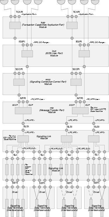
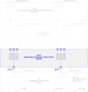
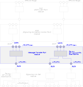
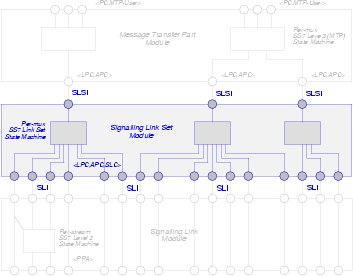
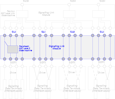
Figure 22 illustrates the organization of STREAMS modules, multiplexing drivers, pseudo-device drivers and real device drivers in the OpenSS7 SS7 stack. At each interface, the equivalent SIGTRAN User Adaptation Layer (UA) can be used. So, for example, between MTP Level 3 and its Users, the M3UA protocol can be employed. Each UA provides the same lower layer interface and upper layer interface. So, M3UA provides an MTP/MTP-User interface at its lower layer interface as well as at its upper layer interface.
7 Hardware Architecture
Figure 23 illustrates the hardware configuration for the OpenSS7 VoIP Switch evaluation platform.
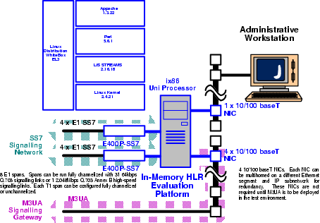
The VoIP Switch prototype platform consists of a high-end ix86 single or multi processor PC loaded with Linux running a 2.4 production kernel, LiS 2.16.18-22 and the OpenSS7 stack software.
As a highly scalable and carrier grade alternative, the prototype system could use the CPC 388 cards running embedded Linux 2.4.18 (NexusWare24) on MPC8260 and performing backplane switching on H.100 and Ethernet rails on PCIMG 2.16 packet bus loaded with NexusWare (Linux 2.4.18), LiS 2.16.18-22 and the OpenSS7 stack software.
SS7 ISUP IMTs and signalling links are terminated on the telephone network side of the device on one of a number of TE410, CPC-384 or CPC-388 cards installed in either platform. On the other side of the platform, RTP connections are terminated on dual Ethernet devices or the PCIMG 2.16 packet bus. Signalling is performed over the same IP connections using BICC/M3UA (NNI), SIP (UNI) or H.245 (UNI). The OpenSS7 complex side of the device is attached directly to the IP backbone and signals to remote BICC switches, SIP proxies/clients or H.323 gatekeepers/clients.
The VoIP Switch prototype device performs conversion between the 64kbps voice channels terminated on the TE410, CPC-384 or CPC-388 cards on the telephone network side of the device to RTP streams on dual 10/100/1000 baseT or PICMG 2.16 packet bus using host or MPC8260 resources.
OAM&P of the prototype platform is performed over an internal LAN connection.
Hardware requirements are as follows:
- 1 x medium end (2.0 GHz) single processor, 19" rack mount, hardened chassis PC, 110 VAC commercial power.
- 2 x E400 Cards (or equivalent).
- 4 x 100baseT Ethernet NICs (3com 905B or equivalent).
For a redundant configuration (two hosts serving the same gateway), twice the hardware is required.
7.1 Interface Devices
The interface device hardware cards listed below are supported for the OpenSS7 Platform. All of the interface device hardware listed here has good price-performance, however, varying levels of performance (and therefore price) is available. These cards are available either directly from the card manufacturer or are also resold by OpenSS7 Corporation.
For the VoIP Switch application, either the CPC 388 cards are recommended. The following interface device hardware is available for the OpenSS7 Platform:
7.1.1 T400P/E400P
The T400P and E400P cards are 4-span T1 or E1 cards manufactured by Varion. These cards were previously manufactured by Digium. Figure 24 shows a picture of a T400P card.
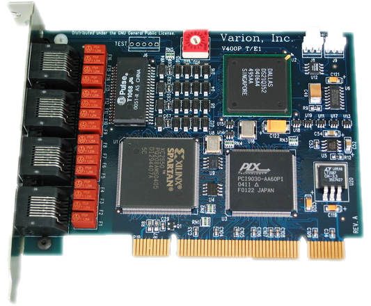
The T400P and E400P cards have the lowest level of signalling performance due to the lack of on-board HDLC functions. Transfers to the host processor over the PCI bus use PCI I/O ports and memory mapping.
Driver
These cards are supported by the X400 driver.
The function of the T/E400P Channel driver is to provide for the termination of 2.048Mbps, 1.544Mbps, 64kbps and 56kbps digital paths. This driver provides direct access to the channelized or unchannelized T1 or E1 digital paths to OpenSS7 media and signalling protocol modules as well as providing T1 or E1 management, framing, coding, alarms, and synchronization.
Features
Following are the features of the T400P and E400P cards:
- 4 T1 or E1 spans per card.
- Dallas framer.
- PLX PCI 9030 PCI bus chip.
- Xilinx Spartan XC2S50 processor.
- Raw transfer of octets from framers to PCI bus.
- Uses OpenSS7 Soft-HDLC engine for SS7, ISDN and ISO.
- 96 channels per card (T400P)
- 124 channels per card (E400P).
- Full span addressable.
Advantages
Following are the advantages of the T400P and E400P cards:
- Low cost.
- PC Compatibility.
- Released by Jim Dixon under the GNU Public License.
- Open Hardware design: schematics, artwork and Gerber plots available.
- Flash programmable Xilinx chip.
- Field upgradable.
- Supports a number of Open Source drivers.
- Asterisk driver support.
Disadvantages
Following are the disadvantages of the T400P and E400P cards:
- Lower performance.
- No on-board HLDC.
- Cannot TDM switch on card or between cards, media channels must be transferred through host to switch between cards.
- I/O Port and Memory Map instead of PCI DMA bus-mastering and burst transfers.
- Does not run on high speed buses.
- No integrated Ethernet for SIGTRAN and VoIP applications.
- Synchronization per-card instead of per-system.
Ultimately, the performance limiting factor of the T400P and E400P cards is the bandwidth of the PCI bus and the ability of the processor to perform Soft-HDLC and TDM switching in software. A 350MHz processor is capable of processing the bandwidth of an entire E400P card (124 signalling links) with a combined link throughput of 8.192 Mbps.
For the OpenSS7 VoIP Switch, this performance is more than adequate. A medium grade 2GHz PC should be capable of handling 2 cards (248 SS7 links) with adequate excess capacity available for background operations.
These cards are very cost-effective and can provide 64kbps SS7 links at average incremental interface cost of approximately $8.00 USD per signalling link.
7.1.2 TE405/410
The TE405/410 cards are 4-span E1/T1 cards manufactured by Digium. These cards are a higher performance replacement for the T400P and E400P cards. Figure 25 shows a picture of a T405P card.
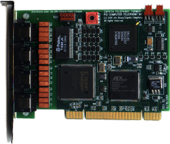
The TE405 and TE410 cards have a low level of signalling performance due to the lack of on-board HDLC functions. However, transfers to the host process over the PCI bus use bus-mastering PCI burst DMA transfers, unlike their T400P and E400P predecessors.
Driver
These cards are supported by the TE400 driver.
The function of the TE405/410 Channel driver is to provide for the termination of 2.048Mbps, 1.544Mbps, 64kbps and 56kbps digital paths. This driver provides direct access to the channelized or unchannelized T1 or E1 digital paths to OpenSS7 media and signalling protocol modules as well as providing T1 or E1 management, framing, coding, alarms, and synchronization.
Features
Following are the features of the TE405 and TE410 cards:
- 4 T1 or E1 spans per card.
- PMC Sierra framer
- PLX PCI 9030 PCI bus chip.
- Xilinx Spartan XC2S50 processor.
- Raw transfer of octets from framers to PCI bus.
- Uses OpenSS7 Soft-HDLC engine for SS7, ISDN and ISO.
- 96 channels per card (T1).
- 124 channels per card (E1).
- Full span addressable.
Advantages
Following are the advantages of the TE405 and TE410 cards:
- Lower cost.
- PCI DMA bus-mastering and burst transfers.
- Flash programmable Xilinx chip.
- Field upgradable.
- Supports a number of Open Source drivers.
- Asterisk driver support.
Disadvantages
Following are the disadvantages of the TE405 and TE410 cards:
- Lower performance, although better than predecessor.
- No on-board HLDC.
- Cannot TDM switch on card or between cards, media channels must be transferred through host to switch between cards.
- No integrated Ethernet for SIGTRAN and VoIP applications.
- Synchronization per-card instead of per-system.
As with their predecessors, the performance limiting factor of the TE405 and TE410 cards is the bandwidth of the PCI bus and the ability of the processor to perform Soft-HDLC and TDM switching in software. A 350MHz processor is capable of processing the bandwidth of an entire TE405 card (124 signalling link) with a combined linke throughput of 8.192 Mbps.
For the OpenSS7 VoIP Switch, this performance is more than adequate. A medium grade 2GHz PC should be capable of handling 2 cards (248 SS7 links) with adequate excess capacity available for background operations.
These cards are cost-effective and can provide 64kbps SS7 links at average incremental interface cost of approximately $12.00 USD per signalling link.
7.1.3 A101/102/104c
The A101/102/104c cards are 1-, 2- and 4-span E1, T1 or J1 cards manufactured by Sangoma. Figure 26 shows a picture of an A101c card.
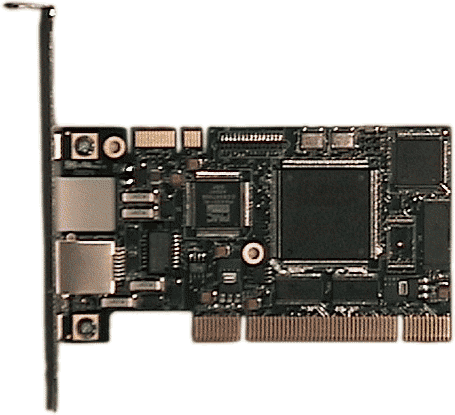
The A10Xc cards have an increased level of signalling performance due to availability of on-board HDLC processing. Transfers to the host are performed using bus-mastering PCI DMA burst transfers for lower host processor overhead. These cards do not support direct on-board TDM switching; neither do they have integrated Ethernet.
Driver
These cards are supported by the A100 driver.
The function of the A100 Channel driver is to provide for the termination of 2.048Mbps, 1.544Mbps, 64kbps and 56kbps digital paths. This driver provides direct access to the channelized or unchannelized T1 or E1 digital paths to OpenSS7 media and signalling protocol modules as well as providing T1 or E1 management, framing, coding, alarms, and synchronization.
Features
Following are the features of the A101c, A102c and A104c cards:
- 1, 2 or 4 E1 spans per card.
- PMC Comet framer.
- Xilinx Spartan XC2S50 processor.
- Raw transfer of octets from framers to PCI bus.
- Can use OpenSS7 Soft-HDLC engines for SS7, ISDN and ISO.
- Also provides for onboard HLDC (SS7 DAEDR/DAEDT AERM/SUERM).
- 24, 48 and 96 channels per card (T1 A101, A102 and A104).
- 31, 62 and 124 channels per card (E1 A101, A102 and A104).
- Full span addressable.
Advantages
Following are the advantages of the A101, A102 and A104 cards:
- Low cost.
- PC Comaptibility.
- Homolgomation and world-wide support.
- Flash programmable Xilinx chip.
- Field upgradable.
- Supports a wide range of Open Source drivers.
- Linux kernel WAN support.
- Asterisk driver support.
Disadvantages
Following are the disadvantages of the A101, A102 and A104 cards:
- Cannot TDM switch on card or between cards, media channels must be transferred through host to switch between cards.
- No integrated Ethernet for SIGTRAN and VoIP applications.
- Synchronization per-card instead of per-system.
The performance limiting factor of the A101c, A102c and A104c cards is the bandwidth of the PCI bus and the ability of the processor to perform TDM switching is software.
For the OpenSS7 VoIP Switch, this performance is more than adequate, particularly as TDM switching is not a requirement for this pure signalling application. Although these cards lack integrated Ethernet support, for the non-redundant switching application, and where interworking between SIGTRAN and SS7 is not required, this is not a limitation.
These cards have excellent price-performance and can provide 64kbps SS7 links at average incremental interface cost of approximately $12.00 USD per signalling link.
7.1.4 Other Interface Cards
Additional interface cards could be implemented in other phases of the project. For additional information, see Optional Hardware Support.
8 Platform Architecture
This section details the platform architecture. The solution platform architecture consists of the computing platform and associated hardware, interfaces and peripherals.
Figure 13 illustrates the solution platform rack configuration.
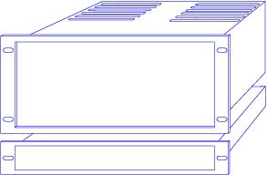
The solution platform consists of the following:
- One hardened PC (2U) chassis per system.
- One 10/100/1000 Mblks (10/100/1000baseT) RJ-45c Layer 2 Ethernet Switch.
Platform Capacity
The PC chassis is equipped with the following: 21
8.1 HP cc3310 Based Platform
8.2 Dell PowerEdge 2650 Based Platform
9 System Architecture
This section details the solution system architecture. The solution system architecture consists of the computing platforms and their placement within the local installation environment.
The solution system has the following requirements:
- 19" rack
- 110 to 220 VAC or -48 VDC electical power.
- Commercial cooling.
- Bantam to RJ48c patch panel.
9.1 HP cc3310 Based System
9.2 Dell PowerEdge 2650 Based System
10 Logistics
10.1 Hardware
10.1.1 Sizing Considerations
10.2 Software
10.3 Consulting
10.4 Schedule
10.4.1 Gate 0 — Concept
10.4.2 Gate 1 — High-Level Design
10.4.3 Gate 2 — Detailed Design
10.4.4 Gate 3 — Development and Implementation
10.4.5 Gate 4 — System Test
10.4.6 Gate 5 — Acceptance Testing
10.4.7 Gate 6 — Support Complete
10.5 Cost
Appendix A Optional Application Support
A.1 Other Solution Architecture
A.1.1 ISDN to ISUP Conversion
Appendix B Optional Network Support
B.1 VoIP Switch Reference Interfaces
Appendix C Optional Protocol Support
C.1 Other Protocol Components
C.1.1 SCCP User Adaptation Layer (SUA) Driver
The SUA driver provides the OpenSS7 VoIP Switch with the ability to act as an SUA AS (Application Server) in conjunction with an SUA SG (Signalling Gateway). In this project, the SG function is performed by existing lab equipment. The SUA driver accepts the transport of the SCCP to SCCP-User interface from the SG to the MGC. The SUA driver links SCTP driver streams underneath it to provide the transport services for exporting the SCCP-User interface. The SUA driver provides the same interfaces to its users as the OpenSS7 SCCP.
The SUA driver is a STREAMS driver that runs in the Linux kernel for maximum performance.
C.1.2 MTP Level 3 Broadband (MTP3b) Module
C.1.3 Service Specific Connection Oriented Protocol (SSCOP) Driver
C.1.4 MTP Level 2 User Adaptation Layer (M2UA) Driver
The M2UA driver provides the OpenSS7 VoIP Switch with the ability to act as an M2UA AS (Application Server) in conjunction with an M2UA SG (Signalling Gateway). In this project, the SG function is performed by existing lab equipment. The M2UA driver accepts the transport of the SL to SL-User interface from the SG to the MGC. The M2UA driver links SCTP driver streams underneath it to provide the transport services for exporting the SL-User interface. The M2UA driver provides the same interface to its users as the OpenSS7 SL module.
Appendix D Optional Software Support
D.1 Operating System Options
D.2 STREAMS Options
D.2.1 Linux Fast-STREAMS (LfS)
Appendix E Optional Hardware Support
E.1 Other Interface Devices
This section provides information on additional interface cards available for use with the OpenSS7 SS7, SIGTRAN, ISDN and VoIP stacks:
E.1.1 ACB56
The ACB56 cards are single V.35 56/64kbps synchronous cards manufactured by SeaLevel Systems and distributed by ICS. Figure A-13 shows a picture of an ACB56 card.
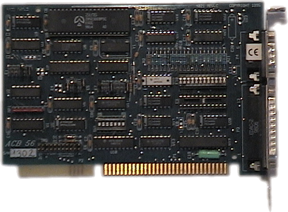
Driver
The driver for the ACB56 card provides, CH, SDL or SDT access to the card. The CH or SDL driver places the Zilog part into transparent mode and passes octets directly off the line to the channel or signalling data link driver. The SDT driver places the Zilog part into HDLC mode and performs SS7 HDLC using the Zilog SCC. The SDT driver performs better, of course, than the CH or SDL drivers, however, the Zilog SCC HDLC is incapable of performing some SS7 functions that are provided by the OpenSS7 SDT (SS7-HDLC) module for the CH or SDL drivers.
Features
Following are some features of the ACB56 card:
- 1 x V.35 56kbps or 64 kbps synchronous port on DB-25 connector.
- DB-25 to N-type cable available.
- 56 kbps or 64kbps DTE mode.
- 56 kbps DCE mode.
- Based on Zilog 80585 Serial Communications Controller (SCC).
- ISA Bus.
- Supports dual-channel ISA DMA.
- Also supports RS-232C although not useful for SS7.
Advantages
Following are the advantages of the ACB56 card:
- Provides V.35 interface where necessary.
The ACB56 card has few advantages. It only provides low-cost V.35 interface where absolutely necessary. Any other V.35 capable card might be a better choice.
Disadvantages
Following are the disadvantages of the ACB56 card:
- ISA bus.
- Low density.
- Limited number of cards per host due to ISA IRQ and DMA limitations.
- Needs external CSU/DSU.
- Does not support TDM voice channels.
Due to its disadvantages, another V.35 card (PCI based, higher density, integrated CSU/DSU) should be considered where V.35 interface is completely necessary.
The OpenSS7 VoIP Switch does not have a requirement for V.35 interface and this card is not used on the deployment platform. If V.35 interface becomes a requirement at a later date, a different card will be selected. The selected card will have a higher density, PCI with PCI DMA and bus-mastering, integrated CSU/DSU, and other features absent from the ACB56 card.
E.1.2 PCA 200E
The PCA 200E card is a 155MHz ATM card manufactured by Marconi (formerly FORE). Figure A-16 shows a picture of an PCA 200E card.
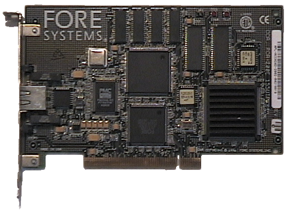
The PCA 200E cards have a good level of signalling performance because they have an on-board 25MHz i960 Intel RISC processor performing cell processing using buffer rings in the same manner as an Ethernet controller.
Driver
Features
Following are the features of the PCA 200E cards:
- 155 MHz ATM, ST/SC SM/MM and RJ-45 UTP 5
- AAL1, AAL2, AAL3 and AAL5 modes.
- Integrated 25 MHz i960 RISC cell processor.
- Enhance SAR Processor (ESP) ASIC
- Special-purpose hardware for AAL5 and AAL3/4, HEC, and CRC calculations.
- Dual-ported RAM and Buffer Ring technique similar to Ethernet Controller.
- Serial communications emulation.
- Supports ABR
- ATM cell processing per ANSI T1S1.5/92-002R3, ITU I.361, ATM Form UNI v3.0, 3.1, 4.0
Advantages
Following are the advantages of the PCA 200E cards:
- Inexpensive (about $200 a card).
- Supports MTP3b.
- Can support 3GPP UMTS Iu User and Control Plane over PVCs.
Disadvantages
Following are the disadvantages of the PCA 200E cards:
- Does not support traditional SS7 links.
- Requires external ATM switch or point-to-point ATM connection.
E.1.3 BRI
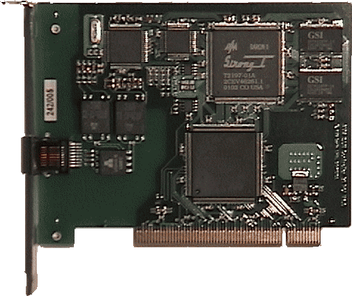
Driver
Features
Following are the features of the BRI cards:
Advantages
Following are the advantages of the BRI cards:
Disadvantages
Following are the disadvantages of the BRI cards:
Appendix F Programmatic Interfaces
Appendix G Platform Sizing
Index
- A101c: A101/102/104c
- A102c: A101/102/104c
- A104c: A101/102/104c
- ACB56: ACB56
- Application architecture: Application Architecture
- BICC: Bearer Independent Call Control (BICC)
- BRI: BRI
- Comet framer: A101/102/104c
- CPC 384: Network Architecture
- CPC 388: Interface Devices
- CPC 388: Hardware Architecture
- CPC 388: Network Architecture
- Dallas framer: T400P/E400P
- Debian: Linux Operating System
- Dell PowerEdge 2650: Dell PowerEdge 2650 Based System
- Dell PowerEdge 2650: Dell PowerEdge 2650 Based Platform
- Document abstract: Preface
- Document audience: Preface
- Document disclaimer: Preface
- Document information: Preface
- Document intent: Preface
- Document objective: Preface
- Document organization: Preface
- Document revisions: Preface
- DUA: DPNSS/DASS User Adaptation Layer (DUA)
- E400P: T400P/E400P
- E400P: Hardware Architecture
- E400P: Signalling Link (SL) Module
- Fedora: Linux Operating System
- GR303/V5.2 User Adaptation Layers: GR303/V5.2 User Adaptation Layers
- GR303UA: GR303 User Adaptation Layer (GR303UA)
- H.245 DL: H.245 Data Link Module
- H.248: H.248/MEGACO Driver
- H.323: H.323 Driver
- Hardware architecture: Hardware Architecture
- HP cc3310: HP cc3310 Based System
- HP cc3310: HP cc3310 Based Platform
- Interface devices: Interface Devices
- Introduction: Introduction
- ISDN: Integrated Services Digital Network (ISDN)
- ISDN DL: Integrated Services Digital Network (ISDN) Data Link (DL) Module
- ISDN User Adaptation Layers: ISDN User Adaptation Layers
- ISUA: ISUP User Adaptation Layer (ISUA)
- ISUP: Integrated Services Digital Network (ISDN) User Part (ISUP)
- ISUP/BICC/ISDN operations maintenance and administration: ISUP/BICC/ISDN Operations Maintenance and Administration
- IUA: ISDN Q.921 User Adaptation Layer (IUA)
- Linux: Linux Operating System
- Linux STREAMS (LiS): Linux STREAMS (LiS)
- LiS: Linux STREAMS (LiS)
- Logistics: Logistics
- M2PA: MTP2 User Peer-to-Peer Adaptation Layer (M2PA)
- M2UA: MTP Level 2 User Adaptation Layer (M2UA) Driver
- M2UA: MTP2 User Part Adaptation Layer (M2UA)
- M2UA: Network Architecture
- M3UA: OpenSS7 SS7 and VoIP Stack
- M3UA: MTP3 User Part Adaptation Layer (M3UA)
- M3UA: Signalling Connection Control Part (SCCP) Driver
- M3UA: Network Architecture
- MEGACO: H.248/MEGACO Driver
- MG: Media Gateway (MG) Driver
- MGCP: MGCP Driver
- MTP: Message Transfer Part (MTP)
- MTP Level 2 User Adaptation Layer (M2UA) Driver: MTP Level 2 User Adaptation Layer (M2UA) Driver
- MTP Level 3 Broadband (MTP3b) Module: MTP Level 3 Broadband (MTP3b) Module
- MTP3b: MTP Level 3 Broadband (MTP3b) Module
- MX: Channel Multiplex Module (MX)
- Network architecture: Network Architecture
- OpenSS7 SS7 and VoIP stack: OpenSS7 SS7 and VoIP Stack
- OpenSwitch call framework application: OpenSwitch Call Framework Application
- Optional application support: Optional Application Support
- Optional hardware support: Optional Hardware Support
- Optional network support: Optional Network Support
- Optional protocol support: Optional Protocol Support
- Optional software support: Optional Software Support
- Other interface cards: Other Interface Cards
- Other interface devices: Other Interface Devices
- Other protocol components: Other Protocol Components
- PCA 200E: PCA 200E
- Platform architecture: Platform Architecture
- Platform sizing: Platform Sizing
- PMC Sierra framer: TE405/410
- Programmatic interfaces: Programmatic Interfaces
- Project drivers: Project Drivers
- Project gates: Gates
- Project objectives and milestones: Objectives and Milestones
- Project phases and timeboxing: Phases and Timeboxing
- Protocol architecture: Protocol Architecture
- Q.703 Annex B: Signalling Data Terminal (SDT) Module
- Q.703 Annex B: Signalling Link (SL) Module
- Q.703 Annex B: Network Architecture
- RedHat: Linux Operating System
- Reference architecture: Reference Architecture
- RTP/RTCP: Real-Time Protocol/Real-Time Control Protocol (RTP/RTCP)
- SCCP: Signalling Connection Control Part (SCCP) Driver
- SCCP User Adaptation Layer (SUA) Driver: SCCP User Adaptation Layer (SUA) Driver
- schedule: Schedule
- Scope: Scope
- SCTP: MTP Level 2 User Adaptation Layer (M2UA) Driver
- SCTP: SCCP User Adaptation Layer (SUA) Driver
- SCTP: Stream Control Transmission Protocol (SCTP)
- SCTP: MTP2 User Part Adaptation Layer (M2UA)
- SCTP: MTP3 User Part Adaptation Layer (M3UA)
- SCTP: SCCP User Adaptation Layer (SUA)
- SCTP: Transaction Capabilities Application Part (TCAP) Driver
- SCTP: Integrated Services Digital Network (ISDN) User Part (ISUP)
- SCTP: Network Architecture
- SDT: Signalling Data Terminal (SDT) Module
- Service Specific Connection Oriented Protocol (SSCOP) Driver: Service Specific Connection Oriented Protocol (SSCOP) Driver
- SIP: Session Initiation Protocol (SIP) Driver
- SIP/H.323 operations maintenance and administration: SIP/H.323 Operations Maintenance and Administration
- SL: Signalling Link (SL) Module
- Software architecture: Software Architecture
- SS7 User Adaptation Layers: SS7 User Adaptation Layers
- SSCOP: Service Specific Connection Oriented Protocol (SSCOP) Driver
- STREAMS: STREAMS Facility
- SUA: SCCP User Adaptation Layer (SUA) Driver
- SUA: SCCP User Adaptation Layer (SUA)
- SuSE: Linux Operating System
- System architecture: System Architecture
- T400P: T400P/E400P
- TALI: Tekelec's Adaptation Layer Interface (TALI)
- TCAP: Transaction Capabilities Application Part (TCAP) Driver
- TCP: Transmission Control Protocol (TCP)
- TE405: TE405/410
- TE405/410: TE410 Channel Driver (X400P-CH)
- TE410: TE405/410
- TE410: Network Architecture
- The OpenSS7 VoIP Switch: The OpenSS7 VoIP Switch
- TUA: TCAP User Adaptation Layer (TUA)
- UDP: User Datagram Protocol (UDP)
- V5UA: V5.2 User Adaptation Layer (V5UA)
- VoIP gateway reference entities: VoIP Switch Reference Entities
- VoIP gateway reference interfaces: VoIP Switch Reference Interfaces
- WhiteBox EL3: Linux Operating System
- Xilinx: A101/102/104c
- Xilinx: TE405/410
- Xilinx: T400P/E400P
Short Contents
- OpenSS7 VoIP Switch
- Executive Overview
- Executive Summary
- Preface
- 1 Introduction
- 2 Application Architecture
- 3 Network Architecture
- 4 Reference Architecture
- 5 Protocol Architecture
- 6 Software Architecture
- 7 Hardware Architecture
- 8 Platform Architecture
- 9 System Architecture
- 10 Logistics
- Appendix A Optional Application Support
- Appendix B Optional Network Support
- Appendix C Optional Protocol Support
- Appendix D Optional Software Support
- Appendix E Optional Hardware Support
- Appendix F Programmatic Interfaces
- Appendix G Platform Sizing
- Index
Table of Contents
- OpenSS7 VoIP Switch
- Executive Overview
- Executive Summary
- Preface
- 1 Introduction
- 2 Application Architecture
- 3 Network Architecture
- 4 Reference Architecture
- 4.1 VoIP Switch Reference Entities
- 4.2 VoIP Switch Reference Interfaces
- 5 Protocol Architecture
- 5.1 Applications
- 5.2 SS7 Stack
- 5.2.1 ISUP/BICC/ISDN Operations Maintenance and Administration
- 5.2.2 Integrated Services Digital Network (ISDN) User Part (ISUP)
- 5.2.3 Transaction Capabilities Application Part (TCAP) Driver
- 5.2.4 Signalling Connection Control Part (SCCP) Driver
- 5.2.5 Global Title Translations (GTT)
- 5.2.6 Message Transfer Part (MTP)
- 5.2.7 Signalling Link (SL) Module
- 5.2.8 Signalling Data Terminal (SDT) Module
- 5.3 SIGTRAN Stack
- 5.3.1 SS7 User Adaptation Layers
- 5.3.1.1 ISUP User Adaptation Layer (ISUA)
- 5.3.1.2 TCAP User Adaptation Layer (TUA)
- 5.3.1.3 SCCP User Adaptation Layer (SUA)
- 5.3.1.4 MTP3 User Part Adaptation Layer (M3UA)
- 5.3.1.5 MTP2 User Part Adaptation Layer (M2UA)
- 5.3.1.6 MTP2 User Peer-to-Peer Adaptation Layer (M2PA)
- 5.3.1.7 Tekelec's Adaptation Layer Interface (TALI)
- 5.3.2 ISDN User Adaptation Layers
- 5.3.3 GR303/V5.2 User Adaptation Layers
- 5.3.1 SS7 User Adaptation Layers
- 5.4 ISDN Stack
- 5.5 VoIP Stack
- 5.6 MG Stack
- 5.7 IP Transport Stack
- 6 Software Architecture
- 7 Hardware Architecture
- 8 Platform Architecture
- 9 System Architecture
- 10 Logistics
- Appendix A Optional Application Support
- Appendix B Optional Network Support
- Appendix C Optional Protocol Support
- Appendix D Optional Software Support
- Appendix E Optional Hardware Support
- Appendix F Programmatic Interfaces
- Appendix G Platform Sizing
- Index
Footnotes
[1] Not necessarily in that order and not necessarily together.
[2] Although some reference is made to capabilities supporting other phases, Phase 1 and Phase 2 are the focus of this document.
[3] This document is a High-Level Design an Proposal document and it meets the internal requirements for passing Gate 1 of Phase 1 and Phase 2 of the VoIP Switch project. An external review of this document by a Beta or Gamma client or sponsor is pending.
[4] OpenSS7 requires a contractual commitment for purchase from a Beta or Gamma client, or funding from a Sponsor of the OpenSS7 Project, before this gate can be passed and development started.
[5] This section is not intended as a Detailed Design, but provides illustration only for these Application Notes. Refer to RFC XXXX for detailed information.
[6] For other hardware alternatives, see Hardware Architecture
[7] Q.699 compliant (ISUP-H.245 interworking) conversion will be performed for H.323. SIP-T compliant ISUP-SIP conversion (RFC 3398) will be performed for SIP.
[8] Initial phases of the OpenSS7 VoIP Switch use the J Interface internal to the platform. Subsequent phases expose the J Interface.
[9] Message Transfer Part streams bound to ISUP MTP-SAPs are linked under the ISUP driver above to form a complete SS7 stack in support of call switching. Message Transfer Part streams bound to SCCP MTP-SAPs are linked under the SCCP driver above to form a complete SS7 stack in support of transaction services.
[10] Initial phases of the OpenSS7 VoIP Switch use the J Interface internal to the platform. Subsequent phases expose the J Interface, see Reference Interface J.
[11] See Reference Interface E.b.
[12] See Reference Interface J.
[13] See Reference Interface E.b.
[14] See Reference Interface J.
[15] See Reference Interface E.b.
[16] H.248.1, "Gateway Control Protocol Version 1", (March 2002), Geneva, IUT-T Telecommunication Standardization Sector of ITU.
[17] See Reference Interface N.
[18] RFC 2705, "Media Gateway Control Protocol (MGCP) Version 1.0," (October, 1999), The
Internet Society.
RFC 3435, "Media Gateway Control Protocol (MGCP) Version 1.0," (January 2003),
The Internet Society.
[19] See Reference Interface N.
[20] At the time that this document what written, GCOM had just announced that it is no longer supporting the Open Source Linux STREAMS package. The OpenSS7 Project continues to support our autoconf/RPM 2.16.18 releases of LiS until such time that Linux Fast-STREAMS is complete and available as a replacement. The newer 2.18 GCOM releases are not supported.
[21] For detailed sizing considerations, see Platform Sizing.
SS7 for the
Common Man
| Home |
© Copyright 1997-2007 OpenSS7 Corporation All Rights Reserved.