SS7 for the
Common Man
Last modified: Sat, 01 Nov 2008 14:12:38 GMT
| Home |
| ||
| ||
| ||
| ||
| ||
NLI Technical Specification
Description: OpenSS7 Project Library Transport NLI
A PDF version of this document is available here.
Network Layer Interface
Network Layer Interface
1 Introduction
The Network Layer Interface (NLI) was developed by Spider Systems, Ltd., (now a division of Emerson Power), and is widely available on many platforms. For example, AIX AIXlink/X.25, HP-UX HP X.25/9000, Solaris Solstice X.25 and SunLink X.25, IRIX IRIS SX.25, PT X.25 and SBE X.25 implement the Network Layer Interface (NLI).
The Network Layer Interface (NLI) was designed to be used directly with standard STREAMS system calls and does not require the use of a cooperating user space shared library. Applications programs directly use the getmsg(2s), getpmsg(2), putmsg(2s), putpmsg(2) and ioctl(2) system calls.1 Nevertheless, user shared object libraries can easily be constructed using this STREAMS service primitive interface.
The system header files that must be included when compiling user applications, or STREAMS drivers and modules that use the interface, are detailed in NLI Header Files.
A user library, libsx25, is provided, not for interfacing to the message primitive service interface, but for providing various helper functions when using the STREAMS service interface. This library is detailed in NLI Library.
1.1 History
The original UNIX® System V Release 3.2 with the Network Service Utilities (NSU) package, defined three levels of interface corresponding to boundaries of the OSI Model, as follows:
- Transport Layer Inteface
-
This interface later turned into the Transport Provider Interface (TPI)
that was standardized by UNIX International and later standardized by the
Open Group.
Two libraries existed in SVR 4 and X/Open: the Transport
Layer Interface (TLI) library from SVR 4 and the X/Open Transport
Interface (XTI) library from the Open Group.
The Open Group also standardized the XTI interface for X.25.
- Network Layer Interface
-
This interface later turned into the Network Provider Interface (NPI)
that was standardized by UNIX International, but was not standardized by
the Open Group. The NPI was used for X.25 as well as CONS in accordance
with X.223.
No library was provided by SVR 4 for this interface; however,
GCOM specified an NPI API Library also
provided by OpenSS7.
For X.25, Spider Systems, Ltd. provided the Network Layer Interface
(NLI) that is the subject of this specification.
- Link Layer Interface
-
This interface later tunred into the Data Link Provider Inteface (DLPI)
that was standardized by UNIX International and later standardized by the
Open Group.
No library was provided by SVR 4 for this interface; however,
GCOM specifies a DLPI API Library also
provided by
OpenSS7.
For X.25, Spider Systems, Ltd. provided the Link Layer Interface
(LLI) that is the subject of a companion specification.
Sun Microsystems has recently specified a DLPI Library for
Solaris 11 that is also provided by
OpenSS7.
- Media Access Control
-
This interface was proposed by NCR Comten as the Communications
Device Interface (CDI) that was not standardized.
SVR 4 provided a Media Access Control (MAC) interface also
supported by
OpenSS7.
Spider Systems, Ltd. X.25 does not directly use an interface at this
level but, instead relies on access at the LLI.
- Wide Area Network
- This interface was proposed by NCR Comten as the Communications Device Interface (CDI) that was not standardized. For X.25, Spider Systems, Ltd. provided the Wide Area Network (WAN) Interface that is the subject of a companion specification.
The Network Layer Interface (NLI) specified by Spider Systems, Ltd. was the most widespread implementation of X.25 found on UNIX® and Unix-like systems.
1.2 Development
Although the Spider Systems, Ltd. Network Layer Interface (NLI) that is the subject of this specification was and is still in widespread use for the implementation of X.25 on UNIX® and Unix-like systems, it must be stressed that this is a legacy interface. It is provided by The OpenSS7 Project only for the purpose of porting legacy applications, drivers and modules to Linux. The following principles should be adhered to:
- The only formal standard interface for X.25 was specified by the Open
Group using the X/Open Transport Interface
library, specified in reference XX25.
This interface is supported by OpenSS7 using the
XX25 module described in XX25 Module.
This interface alone should be used for new applications.
- For intermodule communications, the only industry standard interface for X.25
was specified by UNIX International as the Network Provider
Interface (NPI) specified in reference NPI. This interface is
supported by OpenSS7 directly and using the NPI
module described in NPI Conversion Module.
This interface alone should be used for new inter-module service interfaces.
- For applications interfaces and inter-module service interfaces for CONS
(X.223), the only industry standard interface was specified by UNIX
International as the Network Provider Interface (NPI) specified in
reference NPI. This interface is supported by
OpenSS7 directly and using the CON module
described in CONS Module.
This interface alone should be used by OSI applications, drivers and modules.
- When porting legacy applications, drivers and modules to Linux, the Network Layer Interface (NLI) as specified in this document may be used both for application interface and for inter-module service interfaces.
Note that when porting legacy NLI applications to Linux using the interface specified in this document, that there are many variations in implementation of the NLI as modified by licensors of the Spider Systems, Ltd. implementation. These modifications are ofter incompatible. Some of the incompatibilities are hidden by an X.25 utility library described in NLI Library.
2 Model of the X.25 Packet Layer
The X.25 Packet Layer provides the means to manage the operation of the X.25 network. It is responsible for the routing and management of data exchange between network-user entities.
The NLI defines the services provided by the X.25 packet layer to the X.25 user at the boundary between the X.25 packet layer and the X.25 user entity. The interface consists of a set of messages defined as STREAMS messages that provide access to the X.25 packet layer services, and are transferred between the X.25 user entity and the X.25 packet layer provider.
These messages are of two types: ones that originate from the X.25 user, and other that originate from the X.25 packet layer. The messages that originate from the X.25 user make requests to the X.25 packet layer, or respone to an event of the X.25 packet layer. The messages that originate from the X.25 packet layer, are either confirmations of a request or are indications to the X.25 user that the event has occured. Figure 1 shows the model of the NLI.
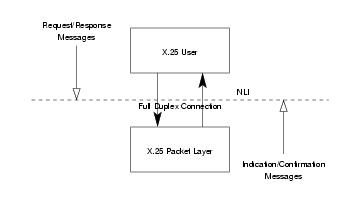
The NLI allows the X.25 packet layer (as a STREAMS driver) to be
configured with an X.25 user (as a STREAMS module) that conforms to the
NLI. An X.25 user can also be a user program that conforms to the NLI and
accesses the X.25 packet layer using putmsg(2s), putpmsg(2),
getmsg(2s), getpmsg(2), and ioctl(2) system calls.
3 NLI Services
The features of the NLI are defined in termsof the services provided by the X.25 packet layer, and the individual messages that may flow between the X.25 user and the X.25 packet layer.
The services supported by the NLI are based on three related modes of communication, X.25 mode, non-X.25 mode, and CONS mode.
3.1 NLI Modes
Packet Level Features
- permanent virtual circuits;
- extended packet sequence numbering;
- D-bit support;
- packet transmission;
- incoming calls barred;
- outgoing calls barred;
- one-way logical channel incoming;
- one-way logical channel outgoing;
- two-way logical channel;
- non-standard default packet sizes;
- non-standard default window sizes;
- default throughput class assignement;
- flow control parameter negotiation;
- throughput class negotiation;
- closed user group;
- bilateral closed user group;
- fast select;
- fast select acceptance;
- reverse charging;
- reverse charging acceptance;
- local charging prevention;
- network user identification selection;
- network user identification override;
- RPOA selection;
- called line address modification;
- call redirection;
- call deflection;
- transit delay;
- protection;
- priority;
- TOA/NPI addressing;
- programmable facilities.
X.25 Facilities
- fast select request;
- fast select with unrestricted response;
- fast select with restricted response;
- reverse charging;
- packet size negotiation;
- window size negotiation;
- closed user groups;
- bilateral closed user groups;
- network user identification;
- RPOA selection;
- called line address modification;
- call redirection;
- call charging;
- programmable facilities;
- DTE facility marker;
- extended address;
- throughput class;
- transit delay;
- expedited data;
- protection;
- priority;
- call user data;
- clear user data.
X.25 Operational Support
- Q-bit support for X.29 services;
- M-bit support for packet segmentation and reassembly;
- D-bit for data delivery confirmation;
- expedited data;
- call charging;
- called line address modification;
- call deflection;
- clear user data.
3.2 NLI Commands
| Command | Description | Section
|
N_CI | xcallf | Connect Request/Indication.
|
N_CC | xccnff | Connect Response/Confirmation.
|
N_Data | xdataf | Data.
|
N_DAck | xdatacf | Data Acknowledgement.
|
N_EData | xeadataf | Expedited Data.
|
N_EAck | xedatacf | Expedited Data Acknowledgement.
|
N_RI | xrstf | Reset Request/Indication.
|
N_RC | xrscf | Reset Response/Confirmation.
|
N_DI | xdiscf | Disconnect Request/Indication.
|
N_DC | xdcnff | Disconnect Confirmation.
|
N_Abort | xabortf | Abort Indication.
|
N_Xlisten | xlistenf | Listen Request/Response.
|
N_Xelisten | xlistenf | Extended Listen Request/Response.
|
N_Xcanlis | xcanlisf | Listen Cancel Request/Response.
|
N_PVC_ATTACH | pvcattf | PVC Attach.
|
N_PVC_DETACH | pvcdetf | PVC Detach.
|
3.3 NLI Data Structures
3.3.1 Addresses
In call requests and responses, it is necessary to specify the X.25 addresses associated with the connection. These addresses consist of the called, calling and responding addresses. A common structure is used for these addresses. The addressing format used by this stricture provides the following information:
- the subnetwork (data link) on which outgoing Connect Requests are to be sent and on which incoming Connect Indications arrive;
- Network Service Access Points (NSAP) and Subnetwork Point of Attachments (SNPA), or Data Terminal Equipment (DTE) addresses and Link Service Access Points (LSAP); and,
- optional formats for the encoding of addresses (NSAP).
3.3.1.1 X.25 Address Format
Addresses are represent using an xaddrf structure. The xaddrf
structure is formatted as follows:
     #define NSAPMAXSIZE 20

     struct xaddrf {
         union {
             uint32_t link_id;
             uint32_t sn_id;
         };
         unsigned char aflags;
         struct lsapformat DTE_MAC;
         unsigned char nsap_len;
         unsigned char NSAP;
     };
The xaddrf structure contains the following members:
link_id- Holds the link number as a
uint32_t. By default,link_idhas a valud of ‘0xFF’. Whenlink_idis ‘0xFF’, Solstice X.25 attempts to match the valled address with an entry in a routing configuration file. If it cannot find a match, it routes the call over the lowest numbered WAN link. sn_id-
Note that in some implementations, the
sn_idfield is declared asunsigned long; however, this causes complications for 32-bit applications running over a 64-bit kernel: i.e., it requires that the data model of the application be known to the kernel module and conversions be supported. Therefore, this field appears in the header file as the 32- vs. 64-bit agnosticuint32_t. aflags- Specifies the options required (or used) by the subnetwork to encode and
interpret addresses. It may have one of the following values:
When theNSAP_ADDR‘0x00’ NSAPis OSI-encoded NSAP address.EXT_ADDR‘0x01’ NSAPis non-OSI-encoded extended address.PVC_LCI‘0x02’ NSAPis a PVC number.PVC_LCI‘0x02’ DTE_MACis the LCI of a PVC.NSAPfield is empty,aflagstakes the value zero (0).2 DTE_MAC- The DTE address, or LSAP as two BCD digits per byte, right justified, or the
PVC_LCIas three BCD digits with two digits per byte, right justified. Holds the DTE address, the Medium Access Control plus Service Access Point (MAC+SAP) address or the LCI. This is binary. See lsapformat. nsap_len- The length in semi-octets of the NSAP as two BCD digits per byte, right
justified.
This indicates the length of the NSAP, if any (and where appropriate), in
semi-octets.
NSAP- The NSAP or address extension (see
aflags) as two BCD digitis per byte, right justified. This carries the NSAP or address extension (see fieldaflags) when present as indicated bynsap_len. This is binary.
3.3.1.2 LSAP Address Format
The lsapformat structure is formatted as follows:.
     #define LSAPMAXSIZE

     struct lsapformat {
         unsigned char lsap_len;
         unsigned char lsap_add[LSAPMAXSIZE];
     };
The fields in this structure are defined as follows:
lsap_len- This gives the length of the DTE address, the MAC+SAP address, or the LCI in
semi-octets. For example for Ethernet, the length is always 14 to indicate the
MAC (12) plush SAP (2). The SAP always follows the MAC address. The DTE can be
up to 15 decimal digits unless X.25(88) and Type Of Address/Numbering Plan
Identification (TOA/NPI) addressing is being used, in which case, it can be up
to 17 decimal digits. For an LCI, the length is 3.
The length of the DTE address or LSAP as two BCD digits per byte, right
justified. An LSAP is always 14 digits long. A DTE address can be up to 15
decimal digtis unless X.25(88) and TOA/NPI addressing is used, in which case it
can be up to 17 decimal digits. A
PVC_LCIis 3 digits long. lsap_add- This holds the DTE, MAC+SAP or LCI, when present, as indicated by
lsap_len. This is binary. The DTE address, LSAP orPVC_LCIas two BCD digits per byte, right justified.
For TOA/NPI the TOA is:
| 0000 | 0 | Network-dependent number or unknown.
|
| 0001 | 1 | International number.
|
| 0010 | 2 | National number.
|
| 0011 | 3 | Network specific number (for use in private networks).
|
| 0100 | 4 | Complementary address without main address.
|
| 0101 | 5 | Alternative address.
|
NPI for other than Alternative address is:
| 0000 | 0 | Network-dependent number or unknown.
|
| 0001 | 1 | ITU-T Recommendation E.164 (digital).
|
| 0010 | 2 | ITU-T Recommendation E.164 (analog).
|
| 0011 | 3 | ITU-T Recommendation X.121.
|
| 0100 | 4 | ITU-T Recommendation F.69 (telex numbering plan).
|
| 0101 | 5 | Private number plan (for private use only).
|
NPI when TOA is Alternative Address is:
| 0000 | 0 | Character string coding to ISO/IEC 646.
|
| 0001 | 1 | OSI NSAP address coded per X.213/ISO 8348.
|
| 0010 | 2 | MAC address per IEEE 802.2/ISO/IEC 8802:1998.
|
| 0011 | 3 | Internet Address per RFC 1166. (i.e. an IPv4 address).
|
3.3.2 CONS Quality of Service Parameters
Negotiable X.25 facilities are supported by the PLP driver. This section describes the request and negotiation of these facilities, and the data structures used by the NLI primitives.
The facilities are broken down into two groups:
- those required for Connection-Oriented Network Service (CONS) support, and
- those requried for non-OSI procedures (X.29, for example).
The CONS quality of service (QOS) parameters supported are the following:
- Throughput Class
- Minimum Throughput Class
- Target Transit Delay
- Maximum Acceptable Transit Delay
- Use of Expedited Data
- Protection
- Receipt Acknolwedgement
CONS-related quality of service parameters are defined in the qosformat
structure. The qosformat structure is formatted as follows:
     #define MAX_PROT 32

     struct qosformat {
         unsigned char reqtclass;
         unsigned char locthroughput;
         unsigned char remthroughput;
         unsigned char reqminthruput;
         unsigned char locminthru;
         unsigned char remminthru;
         unsigned char reqtransitdelay;
         unsigned short transitdelay;
         unsigned char reqmaxtransitdelay;
         unsigned char acceptable;
         unsigned char reqpriority;
         unsigned char reqprtygain;
         unsigned char reqprtykeep;
         unsigned char prtydata;
         unsigned char prtygain;
         unsigned char prtykeep;
         unsigned char reqlowprtydata;
         unsigned char reqlowprtygain;
         unsigned char reqlowprtykeep;
         unsigned char lowprtydata;
         unsigned char lowprtygain;
         unsigned char lowprtykeep;
         unsigned char protection_type;
         unsigned char prot_len;
         unsigned char lowprot_len;
         unsigned char protection[MAX_PROT];
         unsigned char lowprotection[MAX_PROT];
         unsigned char reqexpedited;
         unsigned char reqackservice;
         struct extraformat xstras;
     };
The qosformat structure has the following members:
reqtclass- When non-zero, conveys that throughput negotiation is selected.
locthroughput- Contains the four-bit throughput encoding for the local to remote direction.
remthroughput- Contains the four-bit throughput encoding for the remote to local direction.
reqminthruput- When non-zero, conveys that minimum throughput negotiation is selected.
locminthru- When
reqminthruputis non-zero, conveys the four-bit throughput encoding for the local to remote direction. remminthru- When
reqminthruputis non-zero, conveys the four-bit throughput encoding for the remote to local direction. reqtransitdelay- When non-zero, conveys that target transit delay negotiation is selected.
transitdelay- When
reqtransitdelayis non-zero, conveys the 16-bit value. In a Connect Confirmation, the value of the selected transit delay is placed in this field and is non-zero. reqmaxtransitdelay- When non-zero, conveys that maximum acceptable transit delay negotiation is
selected.
acceptable- When
reqmaxtransitdelayis non-zero, conveys the 16-bit value of the maximum acceptable transit delay.Note: Transit delay selection applies only to Connect Requests. There is no transit dleay QOS parameter in a Connect Response. The correct response when the indicated QOS is unattainable is to make a Disconnect Request. In a Connect Confirmation, the value of the selected transit delay is placed in the
transitdelayfield when such negotiation takes place. reqpriority- When non-zero, conveys that data priority negotiation is selected.
reqprtygain- When non-zero, conveys that gain priority negotiation is selected.
reqprtykeep- When non-zero, conveys that keep priority negotiation is selected.
prtydata- When
reqpriorityis non-zero, contains the 8-bit priority for sending data. prtygain- When
reqprtygainis non-zero, contains the 8-bit priority for gaining a connection. prtykeep- When
reqprtykeepis non-zero, contains the 8-bit priority for keeping a connection. reqlowprtydata- When non-zero, conveys that data low priority negotiation is selected.
This field is only valid on Connect Requests/Indications.
reqlowprtygain- When non-zero, conveys that gain low priority negotiation is selected.
This field is only valid on Connect Requests/Indications.
reqlowprtykeep- When non-zero, conveys that keep low priority negotiation is selected.
This field is only valid on Connect Requests/Indications.
lowprtydata- When
reqlowprtydatais non-zero, contains the 8-bit priority for sending data. This field is only valid on Connect Requests/Indications. lowprtygain- When
reqlowprtygainis non-zero, contains the 8-bit priority to gain a connection. This field is only valid on Connect Requests/Indications. lowprtykeep- When
reqlowprtykeepis non-zero, contains the 8-bit priority to keep a connection. This field is only valid on Connect Requests/Indications. protection_type- When non-zero, conveys that protection negotiation is selected. The field can
be one of the following valuse:
Value Name Meaning 1 PRT_SRCSource address specific. 2 PRT_DSTDestination address specific. 3 PRT_GLBGlobally unique. prot_lenlowprot_len- This field is only valid on Connect Requests/Indications.
protectionlowprotection- This field is only valid on Connect Requests/Indications.
reqexpedited- When non-zero, conveys that expedited data negotiation is selected. For Connect
Indications, a non-zero value implies that the Expedited Data negotiation
facility was present in the incoming call packet, and that its use was requested.
Note: Negotiation is a CONS procedure. When the facility is present and indicates non-use, use cannot be negotiated by Connect Responses. For a description of the use of the
CONS_callfield in Connect Requests and Connect Responses, see Connect Request/Indication, and Connect Response/Confirmation.For incoming or outgoing non-CONS calls (denoted by the
CONS_callflag set to zero (0)), Expedited Data negotiation is not required: interrupt data is always available in X.25. This means that this field is ignored on Connect Requests and Responses for non-CONS calls. reqackservice- When non-zero, conveys that receipt confirmation negotiation is selected. For
Connect Indications, a non-zero value implies that the Receipt Confirmation
negotiation facility was present in the incoming call packet, and that its use
was requested. This field can have one of the following values:
In the case of receipt confirmation by the remote DTE, no acknowledgements are expected or given over the X.25 service interface. In the case of receipt confirmation by the remote application, there is a one-to-one corrrespondence between D-bit data and acknowledgements, with one data acknowlegement being received or sent for each D-bit data packet sent or received over the X.25 service interface.Constant Value Description - 0 No receipt confirmation. RC_CONF_DTE1 Confirmation by the remote terminal. RC_CONF_APP2 Confirmation by the remote application. xstras
3.3.3 Non-OSI X.25 Facilities
Although these are non-OSI facilities, they are also negotiable with CONS. For those NLI applications that require them, the non-OSI facilities supported are as follows:
- non-OSI extended addressing;
- X.25 fast select request/indication with no restriction on response;
- X.25 fast select reqeust/indication with restriction on response;
- X.25 reverse charging;
- X.25 packet size negotiation;
- X.25 window size negotiation;
- X.25 network user identification;
- X.25 recognized private operating agency selection;
- X.25 closed user groups;
- X.25 call deflection; and,
- X.25 programmable facilities.
Non-OSI X.25 Facilities are defined in the extraformat structure. The
extraformat structure is formatted as follows:
#define MAX_NUI_LEN 64 #define MAX_RPOA_LEN 8 #define MAX_CUG_LEN 2 #define MAX_FAC_LEN 32 #define MAX_TARIFFS 4 #define MAX_CD_LEN MAX_TARRIFS * 4 #define MAX_SC_LEN MAX_TARRIFS * 4 #define MAX_MU_LEN 16struct extraformat { unsigned char fastselreq; unsigned char restrictresponse; unsigned char reversecharges; unsigned char pwoptions; unsigned char locpacket; unsigned char rempacket; unsigned char locwsize; unsigned char remwsize; int nsdulimit; unsigned char nui_len; unsigned char nui_field[MAX_NUI_LEN]; unsigned char rpoa_len; unsigned char rpoa_field[MAX_RPOA_LEN]; unsigned char cug_type; unsigned char cug_field[MAX_CUG_LEN]; unsigned char reqcharging; unsigned char chg_cd_len; unsigned char chg_cd_field[MAX_CD_LEN]; unsigned char chg_sc_len; unsigned char chg_sc_field[MAX_SC_LEN]; unsigned char chg_mu_len; unsigned char chg_mu_field[MAX_MU_LEN]; unsigned char called_add_mod; unsigned char call_redirect; struct lsapformat called; unsigned char call_deflect; unsigned char x_fac_len; unsigned char cg_fac_len; unsigned char cd_fac_len; unsigned char fac_field[MAX_FAC_LEN]; };
The extraformat structure has the following members:
fastselreq- For non-OSI services (e.g. X.29), if the X.25 facility fast select is to be
requested or indicated, this field is non-zero. For CONS, the use of fast
select is optional.
restrictresponse- If the resonse to a Connect Request or Indication is to be a Diconnect
Indiciation, this filed is non-zero.
reversecharges- If reverse charging is requested or indicated for a connection, this field is
non-zero. The configuration mod bit
SUB_REVCHARGEhas an impact on whether reverse charging is indicated, since it is possible to select a per-subnetwork policy for reciept of reverse charging. pwoptions- This field is used to indicate per-circuit options. The field is a bitwise OR
of zero or more of the following values:
The field is defined as follows:Name Value Meaning when set. NEGOT_PKT0x01 Packet size negotiation permitted. NEGOT_WIN0x01 Window size negotiation permitted. ASSWERN_HWM0x01 Assert concatentaiton limit. #define NEGOT_PKT 0x01 #define NEGOT_WIN 0x02 #define ASSERT_HWM 0x04The field is used for two reasons:
- The X.25 software always indicates the values of the window and packet
sizes operating on the virtual circuit. The field
pwoptionsfor an incoming call indicates whether these values are negotiable. - In Connect Request/Response message, the NLI user can set
nsdulimit, the limit value for packet concatentation by the X.25 level, to a value different from the limit in the subnetwork configuration database. It is not a negotiable option, so whatever the user requests is used.
- The X.25 software always indicates the values of the window and packet
sizes operating on the virtual circuit. The field
locpacket- When non-zero, contains the local to remote direction packet size.
The default value,
DEF_X25_PKT, is seven (7). rempacket- When non-zero, contains the remote to local direction packet size.
The default value,
DEF_X25_PKT, is seven (7). locwsize- When non-zero, contains the local to remote direction window size.
The default value,
DEF_X25_WIN, is two (2). remwsize- When non-zero, contains the remote to local direction window size.
The default value,
DEF_X25_WIN, is two (2). nsdulimit- When non-zero, and the appropriate bit is set in the
pwoptionsfield, this field is used as the specified concatentaiton limit. nui_len- Valid in Connect Requests and Connect Responses, when non-zero, specifies the
length of the
nui_fieldin octets. The Network User Identification facility is not available on 1980 X.25 networks. nui_field- Contains the Network User Identification (NUI) octets of length
nui_len. rpoa_len- Valid in Connect Requests only. When non-zero, the RPOA DNIC information is
suppplied in the
rpoa_fieldfield and the semi-octets in the field are of this length. rpoa_field- Contains the Recognized Private Operating Agency (RPOA) semi-octets of length
rpoa_len. cug_type- Valid in Connect Requests and Connect Indications only, this field, when
non-zero, is 1 for Closed User Group (CUG) and 2 for Bilateral CUG (two members
only).
Note: Incoming CUG facilities are assumed to have been validated by the network. No further cehcking is performed.
cug_field- Contains the Closed User Group (CUG) semi-octets of length up to four (4)
semi-octets for CUG and four semi-octets (4) for BCUG (Bilateral CUG).
reqcharging- When non-zero in a Connect Request of Connect Indication, call charging is
requested; in a Disconnect Indication of Disconnect Confirmation, the
six fields below will give the charging information.
chg_cd_len- When non-zero, conveys the length of the
chg_cd_fieldfield. chg_cd_field- Conveys the call duration.
chg_sc_len- When non-zero, conveys the length of the
chg_sc_fieldfield. chg_sc_field- Conveys the segment count.
chg_mu_len- When non-zero, conveys the length of the
chg_mu_fieldfield. chg_mu_field- Conveys the monetary unit.
called_add_mod- When non-zero, conveys the reason value for call modification.
call_redirect- When non-zero, conveys the reason for call redirection.
called- When
call_redirectis non-zero, conveys the orignalling called DTE address. call_deflect- Valid in the Disconnect Request and Disconnect Indication, when non-zero,
conveys the reason for call deflection. The
deflectedfield in the Disconnect Request or Indication conveys the DTE address, and if required, the NSAP address to which the call is to be deflected. x_fac_len- Valid in Connect Requests and Connect Indications only,
when non-zero, provides the length of the explicit facility ecnoded strings for
X.25 facilities.
cg_fac_len- Valid in Connect Requests and Connect Indiciations only,
when non-zero, provides the length of the explicit facility encoded strings for
non-X.25 facilities for the calling network.
cd_fac_len- Valid in Connect Requests and Connect Indiciations only,
when non-zero, provides the length of the explicit facility encoded strings for
non-X.25 facilities for the called network.
fac_field- When
x_fac_len,cg_fac_lenorcd_fac_lenare non-zero, contains the X.25 facilities, non-X.25 facilities for the calling network, and/or non-X.25 facilities for the called network.Note: The contents of this field, if supplied, are not validated or acted upon by the code. The X.25 facilities are inserted at the end of any other X.25 facilities that are passed in the Connect Request/Indication (for example, packet or window sizes). If any non-X.25 facilities are supplied, the appropriate marker is inserted before the supplied facilities.
4 NLI Message Primitives
4.1 Connect Request/Indication
Format
The Connect Request and Connect Indication use the xcallf structure.
The control part of the message consists of one M_PROTO message block
containing the xcallf structure.
The data part of the message consists of zero or one M_DATA message blocks
containing the Call User Data (if any).
The xcallf structure is formatted as follows:
     struct xcallf {
         unsigned char xl_type;
         unsigned char xl_command;
         int conn_id;
         unsigned char CONS_call;
         unsigned char negotiate_qos;
         struct xaddrf calledaddr;
         struct xaddrf callingaddr;
         struct qosformat qos;
     };
Usage
The Connect Request or Indication message primitive, N_CI, is used by
the NS user to request a outgoing connection, or by the NS provider to indicate
an incoming connection.
The control part of the message consists of one M_PROTO message block, and
contains the xcallf structure.
The data part of the message consists of zero or one M_DATA message blocks
containing the Call User Data (CUD) when supplied.
Parameters
The xcallf structure contains the following members:
xl_type- Always
XL_CTL. xl_command- Always
N_CI, for both Connect Requests and Connect Indications. conn_id- This field is used only for Connect Indications. When an NS user Stream is
listening, multiple incoming Connect Indications can be pending. This field
indicates the connection identifier for the current Connect Indication for use
by the NS user when responding to this Connection Indication with either a
Connect Response or a Disconnect Request message.
CONS_call- Either X.25 or CONS procedures3 can be used
for calls. When non-zero, this field indicates that CONS procedures are to be
used. When zero, this field indicates that X.25 procedures are to be used.
negotiate_qos- QOS parameters can be negotiated by the peer or left at default values. When
non-zero, this field specifies or indicates that QOS parameters are being
negotiated by the NS user or NS user peer and the pertinent ranges are provided
in the
qosmember. When zero, this field specifies and indicates that default values are to be used for the NS user or were indicated by the NS user peer. calledaddr- Conveys the called address. For outgoing Connect Requests, this is the remote
address to which the call is to be connected. For incoming Connect Indications,
this is the local address to which the call was initiated.
callingaddr- Conveys the calling address. For outgoing Connect Requests, this is the local
address from which the call is to be connected. For incoming Connect
Indications, this is the remote address from which the call was initiated.
qos- Conveys the quality of service parameters and CONS an non-CONS facilities that are requested or indicated.
State
Response
When the Connect Request is issued by the NS user, the expected response from the NS provider is a Connect Conformation or a Disconnect Indication.
When the Connect Indication is issued by the NS provider, the expected response from the NS user is a Connect Response or a Disconnect Request.
Equivalence
The Connect Request message primitive is equivalent to the N_CONN_REQ
primitive of the NPI; the Connect Indication, the N_CONN_IND.
4.2 Connect Response/Confirmation
Format
The Connect Response and Connect Confirmation use the xccnff structure.
The control part of the message consists of one M_PROTO message block
containing the xccnff structure.
The data part of the message consists of zero or one M_DATA message blocks
containing the Call User Data (if any).
The xccnff structure is formatted as follows:
     struct xccnff {
         unsigned char xl_type;
         unsigned char xl_command;
         int conn_id;
         unsigned char CONS_call;
         unsigned char negotiate_qos;
         struct xaddrf responder;
         struct qosformat rqos;
     };
Usage
The Connect Response or Confirmation message primitive, N_CC, is used
by the NS user to response to an incoming connection, or by the NS provider to
confirm an outgoing connection.
The control part of the message consists of one M_PROTO message block, and
contains the xccnff structure.
The data part of the message consists of zero or one M_DATA message block
containing the Call User Data (CUD) when supplied.
Parameters
The xccnff structure contains the following members:
xl_type- Always
XL_CTL. xl_command- Always
N_CC, for both Connect Response and Connect Confirmation. conn_id- This field is only used for Connect Responses. When an NS user Stream is
listening, multiple incoming Connect Indications can be pending. This field
specifies the connection identifier from the Connection Indication to which the
NS user is responding.
CONS_call- Either X.25 or CONS procedures4 can be used
for calls. When non-zero, this field indicates that CONS procedures are to be
used. When zero, this field indicates that X.25 procedures are to be used.
negotiate_qos- QOS parameters can be negotiated by the peer or left at default values. When
non-zero, this field specifies or indicates that QOS parameters are being
negotiated by the NS user or NS user peer and the pertinent ranges are provided
in the
rqosmember. When zero, this field specifies and indicates that default values are to be used for the NS user or were indicated by the NS user peer. responder- Conveys the responding address. For Connect Responses, this is the local
address that is responding to the incoming call. For Connect Confirmations,
this is the remote address that responded to the outgoing call.
rqos- Conveys the negotiated quality of service parameters and CONS an non-CONS facilities in response or confirmation.
State
Response
No response is expected when either the NS user or NS provider issue this primitive.
Equivalence
The Connect Response message primitive is equivalent to the N_CONN_RES
primitive of the NPI; the Connect Confirmation, the N_CONN_CON.
4.3 Data
Format
The Data message uses the xdataf structure.
The control part of the message consists of one M_PROTO message block, and
contains the xdataf structure.
The data part of the message consists of one or more M_DATA message blocks
containing the local or remote NS user data (NSDU).
The xdataf structure is formatted as follows:
     struct xdataf {
         unsigned char xl_type;
         unsigned char xl_command;
         unsigned char More;
         unsigned char setDbit;
         unsigned char setQbit;
     };
Usage
The Data message primitive, N_Data, is used to transfer NS user data
to or from the NS user.
The control part of the message consists of one M_PROTO message block, and
contains the xdataf structure.
The data part of the message consists of one or more M_DATA message blocks
containing the local or remote NS user data (NSDU).
Parameters
The xdataf structure contains the following members:
xl_type- Always
XL_DAT. xl_command- Always
N_Data, for both Data Request and Data Indication. More- When non-zero, this field conveys that a subsequent
N_Datamessage primitive will contain additional data belonging to the same NSDU. When zero, this field conveys that the data contained in the message primitive completes an NSDU. setDbit- Conveys that the D-bit is to be (or was) associated with the NSDU. When the
data portion represents part of an NSDU, the bit must be set or clear on each
request or indication belonging to the same NSDU.
setQbit- Conveys that the Q-bit is to be (or was) associated with the NSDU. When the data portion represents part of an NSDU, the bit must be set or clear on each request or indication belonging to the same NSDU.
State
This message primitive is only valid during the data transfer phase.
Response
No response is expected when either the NS user or NS provider issue this primitive, unless the D-bit is set, in which case a Data Acknowledgement response is expected from the NS provider or NS user, respectively.
Equivalence
The Data message primitive is equivalent to the N_DATA_REQ and
N_DATA_IND primitives of the NPI.
4.4 Data Acknowledgement
Format
The Data Acknowledgement message uses the xdatacf structure.
The control part of the message consists of one M_PROTO message block, and
contains the xdatacf structure.
There is no data part (M_DATA message blocks) associated with this message primitive.
The xdatacf structure is formatted as follows:
     struct xdatacf {
         unsigned char xl_type;
         unsigned char xl_command;
     };
Usage
The Data Acknowledgement message primitive, N_DAck, is used to
request or indicate acknolwedgement of data.
The control part of the message consists of one M_PROTO message block, and
contains the xdatacf structure.
There is no data part (M_DATA message blocks) associated with this message primitive.
Parameters
The xdatacf structure contains the following members:
xl_type- Always
XL_DAT. xl_command- Always
N_DAck.
State
This message primitive is only valid during the data transfer phase.
Response
When receipt confirmation from the remote application is active on a VC, this
message primitive is used to acknowledge a previous N_DAck request or
indication that had the D-bit set. There is a one-to-one correspondence between
D-bit data and acknowledgements, with one Data Acknowledgement being conveyed
for each Data message primitive conveyed. The Data message primitive
acknowledged is always the oldest outstanding Data message primitive that
requested acknowledgement.
For CONS calls, if receipt acknowledgement was negotiated on the connection,
then an acknowledgement is pending for each Data primitive conveyed. However,
to be compatible with previous releases of the NPI, the value of the
reqackservice field in the qos structure can be set to request
that the D-bit signifies receipt confirmation by the remote DTE only, thus
ensuring that no acknowledgements are expected or given.
For non-CONS calls, only when the reqackservice field in the
qos structure has been set to the appropriate value will the Data
Acknolwedgement procedures apply for an D-bit Data requested or indicated.
Otherwise, no acknowledgement is expected or given.
Equivalence
The Data Acknowledgement message primitive is equivalent to the
N_DATACK_REQ and N_DATACK_IND primitives of the NPI.
4.5 Expedited Data
Format
The Expedited Data message uses the xedataf structure.
The control part of the message consists of one M_PROTO message block, and
contains the xedataf structure.
The data part of the message consists of one or more M_DATA message blocks
containing the local or remote expedited NS user data (ENSDU).
The xedataf structure is formatted as follows:
     struct xedataf {
         unsigned char xl_type;
         unsigned char xl_command;
     };
Usage
The Expedited Data message primitive, N_EData, is used to transfer
expedited NS user data to or from the NS user.
The control part of the message consists of one M_PROTO message block, and
contains the xedataf structure.
The data part of the message consists of one or more M_DATA message blocks
containing the local or remote expedited NS user data (ENSDU).
The Expedited Data message primitive, N_EData, is used when expedited
data, carried by an X.25 interrupt packet, corsses the X.25 NLI service
interface from NS provider to user or NS user to provider.
The Expedited Data message is a confirmed primitive and must be acknowledged
before another expedited data unit can be requested or indicated.
Parameters
The xedataf structure contains the following members:
xl_type- Always
XL_DAT. xl_command- Always
N_EData.
State
This message primitive is only valid during the data transfer phase.
Response
When NS user or provider issues this primtive it expectes an Expedited Data Acknowledgement message primitive in reponse. The Expedited Data message is a confirmed primitive and must be acknowledged before another expedited data unit can be requested or indicated.
Equivalence
The Expedited Data message primitive is equivalent to the
N_EXDATA_REQ and N_EXDATA_IND primitives of the NPI.
4.6 Expedited Data Acknowledgement
Format
The Expedited Data Acknowledgement message uses the xedatacf structure.
The control part of the message consists of one M_PROTO message block, and
contains the xedatacf structure.
There is no data part (M_DATA message blocks) associated with this message primitive.
The xedatacf structure is formatted as follows:
     struct xedatacf {
         unsigned char xl_type;
         unsigned char xl_command;
     };
Usage
The Expedited Data Acknowledgement message primitive, N_EAck, is used to
request or indicate acknolwedgement of expedited data.
The control part of the message consists of one M_PROTO message block, and
contains the xedatacf structure.
There is no data part (M_DATA message blocks) associated with this message primitive.
Parameters
The xedatacf structure contains the following members:
xl_type- Always
XL_DAT. xl_command- Always
N_EAck.
State
This message primitive is only valid during the data transfer phase.
Response
The Expedited Data Acknolwedgement message primitive is issued only in confirmation to the Expedited Data message primitive. When an Expedited Data message primitive is delivered to the NS user or provider, the NS provider or user, respectively, must acknowledged the expedited data.
Equivalence
The Expedited Data Acknowledgement message primitive has no equivalent in the NPI.
4.7 Reset Request/Indication
Format
The Reset Request and Reset Indication use the xrstf structure.
The control part of the message consists of one M_PROTO message block
containing the xrstf structure.
There is no data part (M_DATA message blocks) associated with this message primitive.
The xrstf structure is formatted as follows:
     struct xrstf {
         unsigned char xl_type;
         unsigned char xl_command;
         unsigned char originator;
         unsigned char reason;
         unsigned char cause;
         unsigned char diag;
     };
Usage
The Reset Request or Indication message primitive, N_RI, is used by
the NS user to request reset of the connection, or by the NS provider to
indicate a remote reset.
The control part of the message consists of one M_PROTO message block, and
contains the xrstf structure.
There is no data part (M_DATA message blocks) associated with this message primitive.
The X.25 cause and diagnostic octets, cause and diag, are
conveyrs, as well as the CONS originator and reason codes,
which are mapped from the cause and diag. A Reset Request
on a non-CONS call can specify a non-zero cause code. This has
no effect for a CONS call.
Parameters
The xrstf structure contains the following members:
xl_type- Always
XL_CTL. xl_command- Always
N_RI. originator- For a CONS call, contains the CONS originator mapped from the X.25 cause and
diagnostic. This field can have one of the following values:
Constant Value Description NS_UNKNOWN0 Originator is unknown. NS_USER1 Originator is the NS user. NS_PROVIDER2 Originator is the NS provider. reason- For a CONS call, contains the CONS reason, mapped from the X.25 cause and
diagnostic.
This field can have one of the following values when the
originatorisNS_PROVIDER:
The field can have the following values when theConstant Value Description NS_RUNSPECIFIED233 Unspecified reason. NS_RCONGESTION234 Congestion. originatorisNS_USER:
The field can have the following values when theConstant Value Description NS_RESYNC250 Resynchronization. originatorisNS_UNKNOWN:Constant Value Description NS_UNKNOWN0 Unspecified reason. cause- Conveys the X.25 cause octet associated with the reset.
diag- Conveys the X.25 diagnostic octet associated with the reset.
State
This message primitive is valid in the data transfer phase.
Response
A Reset Request and Reset Indication message primitive is an acknowledged service. The NS user expects a Reset Confirmation primitive in response to a Reset Request; the NS provide, a Reset Response primitive in reesponse to a Reset Indication.
A collision between a Reset Indication and a Reset Request is taken to acknolwedge the Reset Request and no Reset Confirmation is then issued.
Equivalence
The Reset Request message primitive is equivalent to the N_RESET_REQ
of the NPI; the Reset Indication, N_RESET_IND.
4.8 Reset Response/Confirmation
Format
The Reset Response and Reset Confirmation use the xrscf structure.
The control part of the message consists of one M_PROTO message block
containing the xrscf structure.
There is no data part (M_DATA message blocks) associated with this message primitive.
The xrscf structure is formatted as follows:
     struct xrscf {
         unsigned char xl_type;
         unsigned char xl_command;
     };
Usage
The Reset Response or Confirmation message primitive, N_RC, is used
by the NS user to respond to a Reset Indication for the connection, or by the NS
provider to confirm a Reset Request.
The control part of the message consists of one M_PROTO message block, and
contains the xrscf structure.
There is no data part (M_DATA message blocks) associated with this message primitive.
Parameters
The xrscf structure contains the following members:
xl_type- Always
XL_CTL. xl_command- Always
N_RC.
State
This message primitive is valid in the data transfer phase.
Response
The Reset Response message primitive is used by the NS user to respond to and acknowledge a previous Reset Indication message primitive from the NS provider. The Reset Confirmation message primitive is used by the NS provider to respond to and acknowledge a previous Reset Request message primitive from the NS user.
Equivalence
The Reset Response message primitive is equivalent to the N_RESET_RES
of the NPI; the Reset Confirmation, N_RESET_CON.
4.9 Disconnect Request/Indication
Format
The Disconnect Request and Disconnect Indication use the xdiscf
structure.
The control part of the message consists of one M_PROTO message block
containing the xdiscf structure.
The data part of the message consists of zero or one M_DATA message blocks
containing the Clear User Data (if any).
The xdiscf structure is formatted as follows:
     struct xdiscf {
         unsigned char xl_type;
         unsigned char xl_command;
         unsigned char originator;
         unsigned char reason;
         unsigned char cause;
         unsigned char diag;
         int conn_id;
         unsigned char indicated_qos;
         struct xaddrf responder;
         struct xaddrf deflected;
         struct qosformat qos;
     };
Usage
The Disconnect Request or Indication message primitive, N_DI, is used
by the NS user to reject an incoming connection or disconnect an existing
connection, or by the NS provider to reject an outgoing connection or disconnect
an existing connection.
The control part of the message consists of one M_PROTO message block, and
contains the xdiscf structure.
The data part of the message consists of zero or one M_DATA message blocks
containing the Clear User Data (CUD) when supplied.
The X.25 cause and diagnostic octets, cause and diag, are
presented, as well as the CONS originator and reason codes
mapped from the X.25 cause and diagnostic. A Disconnect Request for a non-CONS
call can specify a non-zero cause code. This has no effect for a CONS
call.
Parameters
The xdiscf structure contains the following members:
xl_type- Always
XL_CTL. xl_command- Always
N_DI. originator- For a CONS call, contains the CONS originator (NS user, NS provider, or
unknown), mapped from the X.25 cause and diagnostic.
This field can have one of the following values:
Constant Value Description NS_UNKNOWN0 Originator is unknown. NS_USER1 Originator is the NS user. NS_PROVIDER2 Originator is the NS provider. reason- For a CONS call, contains the CONS reason, mapped from the X.25 cause and
diagnostic.
This field can have one of the following values when the
originatorisNS_PROVIDER:
The field can have the following values when theConstant Value Description NS_GENERIC224 General. NS_DTRANSIENT225 Disconnect, transient. NS_DPERMANENT226 Disconnect, permanent. NS_TUNSPECIFIED227 Reject, unspecified, transient. NS_PUNSPECIFIED228 Reject, unspecified, permanent. NS_QOSNATRANSIENT229 Reject, QOS unavailable, transient. NS_QOSNAPERMANENT230 Reject, QOS unavailable, permanent. NS_NSAPTUNREACHABLE232 Reject, NSAP unreachable, transient. NS_NSAPPUNREAHCABLE235 Reject, NSAP unreachable, permanent. originatorisNS_USER:Constant Value Description NU_GENERIC240 General. NU_DNORMAL241 Disconnect, normal. NU_DABNORMAL242 Disconnect, abnormal. NU_DINCOMPUSERDATA243 Disconnect, incomprehensible user data. NU_TRANSIENT244 Reject, transient. NU_PERMANENT245 Reject, permanent. NU_QOSNATRANSIENT246 Reject, QOS unavailable, transient. NU_QOSNAPERMANENT247 Reject, QOS unavailable, permanent. NU_INCOMPUSERDATA248 Reject, Call User Data facility. NU_BADPROTID249 Reject, Bad protocol identifier. cause- Conveys the X.25 cause octet associated with the disconnect.
diag- Conveys the X.25 diagnostic octet associated with the disconnect.
conn_id- When a Disconnect Request is used to refuse and incoming connection, this field
contains the
conn_idfrom the corresponding Connect Indication message primitive. indicated_qos- When non-zero, conveys that facilities and quality of service paraemters are
being indicated.
responder- Conveys the responding address. This is the local responding address in a
Disconnect Request used to refuse an incoming call, and a remote
responding address in a Disconnect Indication refusing an outgoing call.
deflected- When the
call_deflectfield of the associatedqosstructure is non-zero, this field conveys the deflected address. The deflected address is the address of the remote station to which the call is being deflected. This is set by the NS user when deflecting a call with a Disconnect Request refusing an incoming connection; and by the NS provider when an outgoing call has been deflected. qos- Conveys the CONS quality of service parameters and non-OSI facilities associated with the disconnect. This is used currently for the charging information when an existing connection is disconnected, and for the deflection facility when an incoming or outgoing call is being deflected.
State
This primitive is valid in the data transfer phase; it is also valid in the incoming or outgoing connecting phase. The call moves to the disconnect phase.
Response
This primitive is valid in response to a previously sent Connect Request or received Connect Indication message primitive; or, to simply request or indicate disconnection of an existing connection.
When an existing connection is disconnect with a Disconnect Request by the NS user, the NS user expects a Disconnect Confirmation to acknowledge the disconnect. All other message should be discarded from the Stream until the Disconnect Confirmation is received.
When a Disconnect Indication is issued by the NS provider, all messages sent downstream except Connect Request or Connect Response messages are silently discarded.
A disconnect collision can occur, where Disconnect Request and a Disconnect Indication messages collide. In this case, the Disconnect Indication messages is taken as a confirmation and no Disconnect Confirmation message should be expected by the NS user.
Equivalence
The Disconnect Request message primitive is equivalent to the
N_DISCON_REQ of the NPI; the Disconnect Indication,
N_DISCON_IND.
4.10 Disconnect Confirmation
Format
The Disconnect Confirmation uses the xdcnff structure.
The control part of the message consists of one M_PROTO message block,
containing the xdcnff structure.
There is no data part (M_DATA message blocks) associated with this message primitive.
The xdcnff structure is formatted as follows:
     struct xdcnff {
         unsigned char xl_type;
         unsigned char xl_command;
         unsigned char indicated_qos;
         struct qosformat qos;
     };
Usage
The Disconnect Confirmation message primitive, N_DC, is used to confirm a previous
Disconnect Request and provide charging information facilities associated with
a previously established call.
The control part of the message consists of one M_PROTO message block,
containing the xdcnff structure.
There is no data part (M_DATA message blocks) associated with this message primitive.
Parameters
The xdcnff structure contains the following members:
xl_type- Always
XL_CTL. xl_command- Always
N_DC. indicated_qos- When non-zero, conveys that CONS quality of service parameters and non-OSI
facilities are indicated.
qos- Conveys the facilities indicated. This is only used on a Disconnect Confirmation to indicate the charging information facility.
State
This primitive is valid in the disconnecting phase.
Response
This message primitive is only issued by the NS provider. No response is expected when the NS provider issues this primitive.
Equivalence
The Disconnect Confirmation message primitive has no equivalent in NPI.
4.11 Abort Indication
Format
The Abort Indication uses the xabortf structure.
The control part of the message consists of one M_PROTO message block
containing the xabortf structure.
There is no data part (M_DATA message blocks) associated with this message primitive.
The xabortf structure is formatted as follows:
     struct xabortf {
         unsigned char xl_type;
         unsigned char xl_command;
     };
Usage
The Abort Indication message primtiive is used by the X.25 driver in lieue of a
Disconnect Indication, when there is insufficient resources to generate a
Disconnect Indication. Therefore, some NS providers may never issue this
message primitive.
Nevertheless, the NS user must be prepared to receive this message primitive in
liueue of a Disconnect Indication.
The control part of the message consists of one M_PROTO message block
containing the xabortf structure.
There is no data part (M_DATA message blocks) associated with this message primitive.
Parameters
The xabortf structure contains the following members:
xl_type- Always
XL_CTL. xl_command- Always
N_Abort.
State
This message primitive is only valid in the data transfer phase. The call moves to the disconnected phase.
Response
This message primitive is only issued by the NS provider. No response is expected when the NS provider issues this primitive.
Equivalence
The Abort Indication message primitive is equivalent to the
N_DISCON_IND of the NPI.
4.12 Listen Request/Response
Format
The Listen Request and Listen Response use the xlistenf structure.
The control part of the message consists of one M_PROTO or M_PCPROTO
message block, and contains the xlistenf structure.
The data part of the message consists of one or more M_DATA message blocks
containing the call user data and address of interest.
The xlistenf structure is formatted as follows:
     struct xlistenf {
         unsigned char xl_type;
         unsigned char xl_command;
         int lmax;
         int l_result;
     };
The M_DATA message blocks are formatted as follows:
     struct lcud {
         unsigned char l_cumode;
         unsigned char l_culength; /* octets */
         unsigned char l_cubytes[0];
         /* followed by l_culength bytes */
     };
     struct ladd {
         unsigned char l_mode;
         unsigned char l_type;
         unsigned char l_length; /* semi-octets */
         unsigned char l_add[0];
         /* followed by ((l_length+1)>>1) bytes
            containing l_length semi-octets. */
     };
Usage
The Listen Request or Response is used when an NS user wishes to register
interest in incoming calls and the NS provider acknowledges the request.
The control part of the message consists of one M_PROTO or M_PCPROTO
message block, and contains the xlistenf structure.
The data part of the message consists of one or more M_DATA message blocks
containing the call user data and address of interest.
The Listen Request queue is ordered in terms of the amount of listen data supplied. The more a Listen Request asks for, the higher its place in the queue. Connect Indications are sent to the listener whose listening criteria are best matched.
Privileged users can ask for a Listen Request to be placed at the front of the
queue, regardless of the amount of listen data supplied. To do this, the Listen
Request should be sent as a M_PCPROTO message. This is achieved by
setting the RS_HIPRI flag in putmsg(2s). Such requests are
searched in the order in which they arrive.
The system adminstrator controls whether or not listening for incoming calls is a privileged operation. If listening is privileged, incoming calls will be sent only to on listen streams opened by a user with superuser privilege. This prevents other users accepting calls that may contain private information, passwords, and so on.
In systems where privileged and non-privileged listens are allowed:
- Privileged listens have priority.
- A matching but busy privileged listen prevents a search of any non-privileged listens.
Parameters
The xlistenf structure contains the following members:
xl_type- Always
XL_CTL. xl_command- Always
N_Xlisten. lmax- Conveys the maximum number of outstanding Connect Indications that the listening
Stream is willing to accept, for the addresses conveyed in the attached
M_DATAmessage blocks.Listen requests are cummulated but this field is not. The maximum number of outstanding Connect Indications will be reflected by the value of this field for the last successful Listen Request issued by the NS user.
l_result- Conveys the result of the Listen Request in a Listen Response message primitive. An error in the parameters or a lack of resources results in this flag being set to a non-zero value.
The M_DATA portion of the message contains the following members:
l_cumode- Specifies the type of matching.
This field can have one of the following values:
Notes:Constant Value Description X25_DONTCARE1 Represents a wildcard. X25_STARTSWITTH2 Contains a prefix. X25_IDENTITY3 Contains an identity match. - When the
l_cumodeis set toX25_DONTCARE, thel_culengthandl_cubytesfields are ommitted from theM_DATAmessage block.
- When the
l_culength- Specifies the length of the
l_cubytesfield in octets. l_cubytes- Contains the bytes to be matched against the Call User Data (CUD).
l_mode- Specifies the type of matching.
This field can have one of the following values:
Notes:Constant Value Description X25_DONTCARE1 Represents a wildcard. X25_STARTSWITTH2 Contains a prefix. X25_IDENTITY3 Contains an identity match. X25_PATTERN4 Contains a pattern.5 - When the
l_modeis set toX25_DONTCARE, thel_type,l_lengthandl_addfields are ommitted from theM_DATAmessage block. - When the
l_modeis set toX25_PATTERN, thel_addfield can contain the wilcard digits ‘*’ and ‘?’ that have the same effect as these characters in regular expressions: that is, ‘*’ represents zero or more characters of any value, and ‘?’ represents single character of any value. The ‘*’ character is represented by the BCD digit0xFand the ‘?’ character is represented by the BCD digit0xE.
- When the
l_type- This field can have one of the following values:
Constant Value Description X25_DTE1 Contains an X.25 DTE (X.121) address. X25_NSAP2 Contains a CONS NSAP address. l_length- Specifies the length of the
l_addfield in semi-octets. That is, the length of thel_addfield in octets is: ‘((l_length+1)>>1)’. The maximum length for a DTE address is 15 or 17 semi-octets (that is, 8 or 9 octets) depending upon whether TOA/NPI addressing is used. The maximum length for an NSAP address is 20 semi-octets (that is, 10 octets). l_add- Contains the bytes to be matched against the DTE address or the NSAP address.
Each semi-octet is a BCD representation. That is, digits in the range ‘0’ through ‘9’ are represented by
0x0through0x9in the semi-octet position. The first digit occupies the high order nibble of the first octet; the second digit, the low order nibble of the first octet; the third digit, the high order nibble of the second octet; and so on. Ifl_lengthis odd, the low order nibble of the last octet is ignored.When the
l_modefield isX25_PATTERN, a semi-octet of0xFrepresents a ‘*’ wildcard, and a semi-octet of0xErepresents a ‘?’ wildcard.
State
This message primitive is valid in the disconnected phase or during an incoming connecting phase.
Response
When an NS user issues a Listen Request, the NS user expects a Listen Response message primitive from the NS provider.
Equivalence
The Listen Request message primitive is equivalent to the
N_BIND_REQ of the NPI; the Listen Response, N_BIND_ACK.
4.13 Extended Listen Request/Response
Format
The Extended Listen Request and Extended Listen Response use the xlistenf
structure.
The control part of the message consists of one M_PROTO or M_PCPROTO
message block, and contains the xlistenf structure.
The data part of the message consists of one or more M_DATA message blocks
containing the call user data and address of interest.
The xlistenf structure is formatted as follows:
     struct xlistenf {
         unsigned char xl_type;
         unsigned char xl_command;
         int lmax;
         int l_result;
     };
The M_DATA message blocks are formatted as follows:
     struct lcud {
         unsigned char l_cumode;
         unsigned char l_culength; /* octets */
         unsigned char l_cubytes[0];
         /* followed by l_culength bytes */
     };
     struct lsn {
         unsigned char l_snmode;
         unsigned char l_snlen;
         unsigned char l_snid[0];
         /* followed by l_snlen bytes */
     };
     struct ladd {
         unsigned char l_mode;
         unsigned char l_type;
         unsigned char l_length; /* semi-octets */
         unsigned char l_add[0];
         /* followed by ((l_length+1)>>1) bytes
            containing l_length semi-octets. */
     };
Usage
The Extended Listen Request or Response is used when an NS user wishes to
register interest in incoming calls and the NS provider acknowledges the
request. The control part of the message consists of one M_PROTO or
M_PCPROTO message block, and contains the xlistenf structure.
The data part of the message consists of one or more M_DATA message blocks
containing the call user data and address of interest.
Parameters
The xlistenf structure contains the following members:
xl_type- Always
XL_CTL. xl_command- Always
N_Xelisten. lmax- Conveys the maximum number of outstanding Connect Indications that the listening
Stream is willing to accept, for the addresses conveyed in the attached
M_DATAmessage blocks.Listen requests are cummulated but this field is not. The maximum number of outstanding Connect Indications will be reflected by the value of this field for the last successful Listen Request issued by the NS user.
l_result- Conveys the result of the Listen Request in a Listen Response message primitive. An error in the parameters or a lack of resources results in this flag being set to a non-zero value.
The M_DATA portion of the message contains the following members:
l_cumode- Specifies the type of matching.
This field can have one of the following values:
Notes:Constant Value Description X25_DONTCARE1 Represents a wildcard. X25_MATCH4 Contains a pattern match.6 - When the
l_cumodeis set toX25_DONTCARE, thel_culengthandl_cubytesfields are ommitted from theM_DATAmessage block.
- When the
l_culength- Specifies the length of the
l_cubytesfield in octets. l_cubytes- Contains the bytes to be matched against the Call User Data (CUD).
l_snmode- Specifies the matching mode.
This field can have one of the following values:
Notes:Constant Value Description X25_DONTCARE1 Represents a wildcard. X25_MATCH4 Contains a pattern match.7 - When the
l_modeis set toX25_DONTCARE, thel_snlenandl_snidfields are ommitted from theM_DATAmessage block.
- When the
l_snlenl_snidl_mode- Specifies the type of matching.
This field can have one of the following values:
Notes:Constant Value Description X25_DONTCARE1 Represents a wildcard. X25_MATCH4 Contains a pattern match.8 - When the
l_modeis set toX25_DONTCARE, thel_type,l_lengthandl_addfields are ommitted from theM_DATAmessage block.
- When the
l_type- This field can have one of the following values:
Constant Value Description X25_DTE1 Contains an X.25 DTE (X.121) address. X25_NSAP2 Contains a CONS NSAP address. l_length- Specifies the length of the
l_addfield in semi-octets. That is, the length of thel_addfield in octets is: ‘((l_length+1)>>1)’. The maximum length for a DTE address is 15 or 17 semi-octets (that is, 8 or 9 octets) depending upon whether TOA/NPI addressing is used. The maximum length for an NSAP address is 20 semi-octets (that is, 10 octets). l_add- Contains the bytes to be matched against the DTE address or the NSAP address.
State
This message primitive is valid in the disconnected phase or during an incoming connecting phase.
Response
When an NS user issues a Listen Request, the NS user expects an Extended Listen Response message primitive from the NS provider.
Equivalence
The Extended Listen Request message primitive is equivalent to the
N_BIND_REQ of the NPI; the Extended Listen Response,
N_BIND_ACK.
4.14 Listen Cancel Request/Response
Format
The Listen Cancel Request and Listen Cancel Response use the xcanlisf
structure.
The control part of the message consists of one M_PROTO message block
containing the xcanlisf structure.
There is no data part (M_DATA message blocks) associated with this message primitive.
The xcanlisf structure is formatted as follows:
     struct xcanlisf {
         unsigned char xl_type;
         unsigned char xl_command;
         int c_result;
     };
Usage
The Listen Cancel Request message primitive is used by the NS user to cancel
listening on any address.
The Listen Cancel Request removes all listen addresses from the Stream. There
is no way of cancelling a Listen Request on a particular address; this message
is probably used when the use of the Stream is about to be changed by the NS
user.
The control part of the message consists of one M_PROTO message block
containing the xcanlisf structure.
There is no data part (M_DATA message blocks) associated with this message primitive.
Parameters
The xcanlisf structure contains the following members:
xl_type- Always
XL_CTL. xl_command- Always
N_Xcanlis. c_result- Conveys the result of the Listen Cancel Request in a Listen Cancel Response message primitive. An failure to cancel a listen request results in this flag being set to a non-zero value. A Listen Cancel Request may fail because no listen was in effect, or a Connect Indication is outstanding.
State
This message primitive is valid in the disconnected phase.
Response
When an NS user issues a Listen Cancel Request, the NS user expects a Listen Cancel Response message primitive from the NS provider.
Equivalence
The Listen Cancel Request message primitive is equivalent to the
N_UNBIND_REQ of the NPI; the Listen Cancel Response,
N_OK_ACK.
4.15 PVC Attach
Format
The PVC Attach uses the pvcattf structure.
The control part of the message consists of one M_PROTO message block
containing the pvcattf structure.
There is no data part (M_DATA message blocks) associated with this message primitive.
The pvcattf structure is formatted as follows:
     struct pvcattf {
         unsigned char xl_type;
         unsigned char xl_command;
         unsigned short lci;
         union {
             uint32_t link_id;
             uint32_t sn_id;
         };
         unsigned char reqackservice;
         unsigned char reqnsdulimit;
         int nsdulimit;
         int result_code;
     };
Usage
The PVC Attach message primitive is used by the NS user when requesting an
attachment of the Stream to a PVC. The NS provider uses the PVC Attach message
primitive to acknolwedge a previous PVC Attach message primitive issued by the
NS user.
The control part of the message consists of one M_PROTO message block
containing the pvcattf structure.
There is no data part (M_DATA message blocks) associated with this message primitive.
Parameters
The pvcattf structure contains the following members:
xl_type- Always
XL_CTL. xl_command- Always
N_PVC_ATTACH. lci- Conveys the logical channel identifier (LCI) of the PVC.
link_id- Conveys the link identifier for the PVC. This is a Solstice X.25 specific
field.
The
link_idandsn_idfields are equivalent, with a slightly different name and format for Solstice X.25. sn_id- Conveys the subnetwork identifier for the PVC. This is the non-Solstice X.25
specific field.
This field is sometimes specified as a
unsigned long. It has been declared as anuint32_tto support compatibility of 32-bit applications running over a 64-bit kernel. reqackservice- When non-zero, conveys that the receipt confirmation service is requested by the
use of the D-bit. This field can have one of the following values:
In the case of receipt confirmation by the remote station, no acknowledgements are expected or given over the X.25 NLI service interface. For receipt confirmation by the remote application, there is a one-to-one correspondence between D-bit data and acknolwedgements passing in opposite directions. One data acknowledgement is received or sent for each D-bit data packet sent or received over the X.25 NLI service interface.Constant Value Description - 0 No receipt confirmation. RC_CONF_DTE1 Confirmation by the remote terminal. RC_CONF_APP2 Confirmation by the remote application. reqnsdulimit- When non-zero, conveys that an NSDU concantenation limit is asserted and the
nsdulimitfield is valid. nsdulimit- When non-zero, conveys the packet concatenation limit for NSDUs when the
reqnsdulimitfield is also non-zero. result_code- When the PVC Attach message primitive is used by the NS provider to acknowledge
a previous PVC Attach message primitive issued by the NS user, this field is
non-zero when an error has been encountered that prevents the attachment of the
PVC.
This field can have one of the following values:
Constant Value Description PVC_SUCCESS0 Operation was successful. PVC_NOSUCHSUBNET1 Subnetwork not configured. PVC_CFGERROR2 LCI not in range, no PVCs. PVC_NODBELEMENTS3 No database available. PVC_PARERROR4 Error in request parameters. PVC_BUSY6 PVC in non-attach state. PVC_CONGESTION7 Resources unavailable. PVC_WRONGSTATE8 State wrong for function. PVC_NOPERMISSION9 Inadequate permissions. PVC_LINKDOWN10 The link has gone down. PVC_RMTERROR11 No reponse from remote. PVC_USRERROR12 User interface error detected. PVC_INTERROR13 Internal error. PVC_NOATTACH14 Not attached yet. PVC_WAIT15 Wait code, not to user.
State
This message primitive is valid in the disconnected phase.
Response
When an NS user issues a PVC Attach, the NS user expects a PVC Attach message primitive from the NS provider in response.
Equivalence
The PVC Attach message primitive is equivalent to the
N_CONN_REQ and N_CONN_CON of the NPI.
4.16 PVC Detach
Format
The PVC Detach uses the pvcdetf structure.
The control part of the message primitive consists of one M_PROTO message
block containing the pvcdetf structure.
There is no data part (M_DATA message blocks) associated with this message primitive.
The pvcdetf structure is formatted as follows:
     struct pvcdetf {
         unsigned char xl_type;
         unsigned char xl_command;
         int reason_code;
     };
Usage
The PVC Detach message primitive, N_PVC_DETACH, is used when an NS
user wishes to detach from a currently attached PVC.
The control part of the message primitive consists of one M_PROTO message
block containing the pvcdetf structure.
There is no data part (M_DATA message blocks) associated with this message primitive.
Parameters
The pvcdetf structure contains the following members:
xl_type- Always
XL_CTL. xl_command- Always
N_PVC_DETACH. reason_code- When the PVC Detach message primitive is used by the NS provider to acknowledge
a previous PVC Detach message primitive issued by the NS user, this field is
non-zero when an error has been encountered that prevents detaching the PVC.
This field can have one of the following values:
Constant Value Description PVC_SUCCESS0 Operation was successful. PVC_NOSUCHSUBNET1 Subnetwork not configured. PVC_CFGERROR2 LCI not in range, no PVCs. PVC_NODBELEMENTS3 No database available. PVC_PARERROR4 Error in request parameters. PVC_BUSY6 PVC in non-attach state. PVC_CONGESTION7 Resources unavailable. PVC_WRONGSTATE8 State wrong for function. PVC_NOPERMISSION9 Inadequate permissions. PVC_LINKDOWN10 The link has gone down. PVC_RMTERROR11 No reponse from remote. PVC_USRERROR12 User interface error detected. PVC_INTERROR13 Internal error. PVC_NOATTACH14 Not attached yet. PVC_WAIT15 Wait code, not to user.
State
This message primitive is valid in the PVC attached phase.
Response
When an NS user issues a PVC Detach, the NS user expects a PVC Detach message primitive from the NS provider in response.
Equivalence
The PVC Detach message primitive is equivalent to the
N_DISCON_REQ of the NPI.
5 NLI Input-Output Controls
5.1 Input-Output Control Data Structures
5.2 Input-Output Control Commands
N_snident | - Configure a newly linked driver. Also N_linkent on Sun.
|
N_snmode | -
|
N_snconfig | - Configure wlcfg database for a subnetwork. Also N_linkconfig on Sun.
|
N_snread | - Also N_linkread on Sun.
|
N_getstats | - read X.25 global (multiplexer) statistics.
|
N_zerostats | - reset X.25 global (multiplexer) statistics.
|
N_putpvcmap | - change per VC packet and window sizes.
|
N_getpvcmap | - get default packet and window sizes.
|
N_getVCstatus | - get per VC state and statistics.
|
N_getVCstats | - get per VC statistics. Sun only.
|
N_getnliversion | -
|
N_getoneVCstats | - get status and statisics for VC associated with the current stream. Sun only.
|
N_traceon | - start packet level tracing.
|
N_traceoff | - stop packet level tracing.
|
N_nuimsg | -
|
N_nuiput | - store a set of NUI mappings.
|
N_nuidel | - delete specific NUI mapping.
|
N_nuiget | - read specific NUI mapping.
|
N_nuimget | - read all NUI mappings.
|
N_nuireset | - delete all NUI mappings.
|
N_zeroVCstats | - reset per VC statistics.
|
N_putx32map | -
|
N_getx32map | -
|
N_getSNIDstats | - retrieve per subnetwork statistics. Also N_getlinkstats on Sun.
|
N_zeroSNIDstats | - reset per subnetwork statistics.
|
N_setQOSDATPRI | -
|
N_resetQOSDATPRI | -
|
N_X25_ADD_ROUTE | - add a new route or update an existing route. Sun only.
|
N_X25_FLUSH_ROUTE | - clear all entries from the routing table. Sun only.
|
N_X25_GET_ROUTE | - obtain routing information for a specific address. Sun only.
|
N_GET_NEXT_ROUTE | - obtain routing information for next route in the routing table. Sun only.
|
N_RM_ROUTE | - remove a specific route. Sun only.
|
5.2.1 N_snident
The N_snident input-output control identifies the subnetwork. This is
performed by indicating the lower multiplex identifier returned from the
I_LINK STREAMS operation and assigning a subnetwork identifier and
a dl_sap and dl_max_conind to bind.
Format
The argument to the N_snident input-output control is a pointer to a
xll_reg structure, formatted as follows:
     struct xll_reg {
         uint32_t snid;
         uint32_t lmuxid;
         uint16_t dl_sap;
         uint16_t dl_max_conind;
     };
Parameters
The xll_reg structure contains the following members:
snid- Specifies the subnetwork identifier to assign to the data link.
lmuxid- Identifies the data link as a linked Stream beneath the lower multiplex.
dl_sap- Specifies the DLSAP to bind the Stream.
dl_max_conind- Specifies the maximum number of connection indications to bind to the Stream.
5.2.2 N_snmode
The N_snmode input-output control adjusts only the subscription mode
bits. When rd_wr is set to read, the subscription mode bits (see the
SUB_MODES member in the wlcfg structure) are read; when set to
write, the mode bits are written.
Format
The argument to the N_snmode input-output control is a pointer to a
snoptformat structure, formatted as follows:
     struct snoptformat {
         uint32_t U_SN_ID;
         uint16_t newSUB_MODES;
         uint8_t rd_wr;
     };
Parameters
The snoptformat structure contains the following members:
U_SN_ID- Specifies the subnetwork identifier of the data link whose modes are to be read
or written.
newSUB_MODES- Contains the read or written subnetwork modes. This can contain a bitmask of
zero or more of the following bits:
0 SUB_EXTENDEDSubscribe extended facilities. 1 BAR_EXTENDEDBar extended facilities. 2 SUB_FSELECTSubscribe fast select. 3 BAR_FSELECTBar fast select. 4 SUB_FSRRESPSubscribe fast select with restriction on response. 5 SUB_REVCHARGESubscribe reverse charging. 6 SUB_LOC_CHG_PREVSubscribe local charge prevention. 7 BAR_INCALLBar incoming calls. 8 BAR_OUTCALLBar ougoing calls. 9 SUB_TOA_NPI_FMTSubscribe TOA/NPI address extensions. 10 BAR_TOA_NPI_FMTBar TOA/NPI address extensions. 11 SUB_NUI_OVERRIDESubscribe NUI override. 12 BAR_CALL_X32_REGBar calls while X.32 registration in progress. rd_wr- Specifies whether to read or write the subnetwork modes.
5.2.3 N_snconfig
The N_snconfig input-output control is used to configure a data link
connected to a subnetwork, but subnetwork identifier.
Format
The argument to the N_snconfig input-output control is a pointer to a
wlcfg structure, formatted as follows:
     struct wlcfg {
         uint32_t U_SN_ID;
         uint8_t NET_MODE;
         uint8_t X25_VSN;
         uint8_t L3PLPMODE;
         uint16_t LPC;
         uint16_t HPC;
         uint16_t LIC;
         uint16_t HIC;
         uint16_t HTC;
         uint16_t LOC;
         uint16_t HOC;
         uint16_t NPCchannels;
         uint16_t NICchannels;
         uint16_t NTCchannels;
         uint16_t NOCchannels;
         uint16_t Nochnls;
         uint8_t THISGFI;
         uint8_t LOCMAXPKTSIZE;
         uint8_t REMMAXPKTSIZE;
         uint8_t LOCDEFPKTSIZE;
         uint8_t REMDEFPKTSIZE;
         uint8_t LOCMAXWSIZE;
         uint8_t REMMAXWSIZE;
         uint8_t LOCDEFWSIZE;
         uint8_t REMDEFWSIZE;
         uint16_t MAXNSDULEN;
         int16_t ACKDELAY;
         int16_t T20value;
         int16_t T21value;
         int16_t T22value;
         int16_t T23value;
         int16_t Tvalue;
         int16_t T25value;
         int16_t T26value;
         int16_t T28value;
         int16_t idlevalue;
         int16_t connectvalue;
         uint8_t R20value;
         uint8_t R22value;
         uint8_t R23value;
         uint8_t R28value;
         uint16_t localdelay;
         uint16_t accessdelay;
         uint8_t locmaxthclass;
         uint8_t remmaxthclass;
         uint8_t locdefthclass;
         uint8_t remdefthclass;
         uint8_t locminthclass;
         uint8_t remminthclass;
         uint8_t CUG_CONTROL;
         uint16_t SUB_MODES;
         struct {
             uint16_t SNMODES;
             uint8_t intl_addr_recogn;
             uint8_t intl_prioritised;
             uint8_t dnic1;
             uint8_t dnic2;
             uint8_t prty_encode_control;
             uint8_t prty_pkt_forced_value;
             uint8_t src_addr_control;
             uint8_t dbit_control;
             uint8_t thclass_neg_to_def;
             uint8_t thclass_type;
             uint8_t thclass_wmap[16];
             uint8_t thclass_pmap[16];
         } psdn_local;
         struct lsapformat local_address;
     };
Parameters
The wlcfg structure contains the following members:
U_SN_IDNET_MODEX25_VSNL3PLPMODELPCHPCLICHICHTCLOCHOCNPCchannelsNICchannelsNTCchannelsNOCchannelsNochnlsTHISGFILOCMAXPKTSIZEREMMAXPKTSIZELOCDEFPKTSIZEREMDEFPKTSIZELOCMAXWSIZEREMMAXWSIZELOCDEFWSIZEREMDEFWSIZEMAXNSDULENACKDELAYT20valueT21valueT22valueT23valueTvalueT25valueT26valueT28valueidlevalueconnectvalueR20valueR22valueR23valueR28valuelocaldelayaccessdelaylocmaxthclassremmaxthclasslocdefthclassremdefthclasslocminthclassremminthclassCUG_CONTROLSUB_MODESpsdn_local-
SNMODESintl_addr_recognintl_prioritiseddnic1dnic2prty_encode_controlprty_pkt_forced_valuesrc_addr_controldbit_controlthclass_neg_to_defthclass_typethclass_wmapthclass_pmap
local_address
5.2.4 N_snread
The N_snread input-output control is used to read the configuration
information for a specified subnetwork identifier.
Format
The argument to the N_snread input-output control is a pointer to a
wlcfg structure, see N_snconfig.
Parameters
See N_snconfig.
5.2.5 N_getstats
The N_getstats input-output control is used to collect the global
statistics.
Format
The argument to the N_getstats input-output control is a pointer to a
buffer aread containing 101 32-bit unsigned integer values.
Parameters
The buffer area contains 101 32-bit unsigned integer values as follows:
| 0 | cll_in_g | Calls received and indicated.
|
| 1 | cll_out_g | Calls sent.
|
| 2 | caa_in_g | Calls established outgoing.
|
| 3 | caa_out_g | Calls established incoming.
|
| 4 | ed_in_g | Interrupts received.
|
| 5 | ed_out_g | Interrupts sent.
|
| 6 | rnr_in_g | Receiver not ready received.
|
| 7 | rnr_out_g | Receiver not ready sent.
|
| 8 | rr_in_g | Receiver ready received.
|
| 9 | rr_out_g | Receiver ready sent.
|
| 10 | rst_in_g | Resets received.
|
| 11 | rst_out_g | Resets sent.
|
| 12 | rsc_in_g | Reset confirms received.
|
| 13 | rsc_out_g | Reset confirms sent.
|
| 14 | clr_in_g | Clears received.
|
| 15 | clr_out_g | Clears sent.
|
| 16 | clc_in_g | Clear confirms received.
|
| 17 | clc_out_g | Clear confirms sent.
|
| 18 | cll_coll_g | Call collision count, not rejected.
|
| 19 | cll_uabort_g | Calls aborted by user before sent.
|
| 20 | rjc_buflow_g | Calls rejected no buffers before sent.
|
| 21 | rjc_coll_g | Calls rejected collision DCE mode.
|
| 22 | rjc_failNRS_g | Calls rejected negative NRS response.
|
| 23 | rjc_lstate_g | Calls rejected link disconnecting.
|
| 24 | rjc_nochnl_g | Calls rejected no local channels left.
|
| 25 | rjc_nouser_g | Calls rejected no user on NSAP.
|
| 26 | rjc_remote_g | Calls rejected by remote responder.
|
| 27 | rjc_u_g | Calls rejected by NS user.
|
| 28 | dg_in_g | Diagnostic packets received.
|
| 29 | dg_out_g | Diagnostic packets sent.
|
| 30 | p4_ferr_g | Format errors in P4.
|
| 31 | rem_perr_g | Remote protocol errors.
|
| 32 | res_ferr_g | Restart format errors.
|
| 33 | res_in_g | Restarts received (including DTE/DXE).
|
| 34 | res_out_g | Restarts sent (including DTE/DXE).
|
| 35 | vcs_labort_g | Circuits aborted by link event.
|
| 36 | r23exp_g | Circuits hung by R23 expiry.
|
| 37 | l2conin_g | Link level connection established.
|
| 38 | l2conok_g | LLC connections accepted.
|
| 39 | l2conrej_g | LLC connections rejected.
|
| 40 | l2refusal_g | LLC connect requests refused.
|
| 41 | l2lzap_g | Operator requests to kill link.
|
| 42 | l2r20exp_g | R20 retransmission expiry.
|
| 43 | l2dxeexp_g | DXE connect expiry.
|
| 44 | l2dxebuf_g | DXE resolve abort, no buffers.
|
| 45 | l2noconfig_g | No configuration base.
|
| 46 | xiffnerror_g | Upper interface bad M_PROTO type.
|
| 47 | xintdisc_g | Internal disconnecte events.
|
| 48 | xifaborts_g | Upper interface abort_vc called.
|
| 49 | PVCusergone_g | Count of non-user interactions.
|
| 50 | max_opens_g | Highest number of simultaneous opens.
|
| 51 | vcs_est_g | Virtual circuits established since reset.
|
| 52 | bytes_in_g | Bytes received.
|
| 53 | bytes_out_g | Bytes sent.
|
| 54 | dt_in_g | Data packets received.
|
| 55 | dt_out_g | Data packets sent.
|
| 56 | res_conf_in_g | Restart confirms received.
|
| 57 | res_conf_out_g | Restart confirms sent.
|
| 58 | reg_in_g | Registration requests received.
|
| 59 | reg_out_g | Registration requests sent.
|
| 60 | reg_conf_in_g | Registration confirms received.
|
| 61 | reg_conf_out_g | Registration confirms sent.
|
| 62 | l2r28exp_g | R28 retransmission expiries.
|
| 63 | Cantlzap_g | Operator link reset refused.
|
| 64 | L2badcc_g | -
|
| 65 | L2baddcnf_g | -
|
| 66 | L3T25timeouts_g | -
|
| 67 | L3badAE_g | -
|
| 68 | L3badT20_g | -
|
| 69 | L3badT24_g | -
|
| 70 | L3badT25_g | -
|
| 71 | L3badT28_g | -
|
| 72 | L3badevent_g | -
|
| 73 | L3badgfi_g | -
|
| 74 | L3badlstate_g | -
|
| 75 | L3badltock2_g | -
|
| 76 | L3badrandom_g | -
|
| 77 | L3badxtock0_g | -
|
| 78 | L3clrbadstate_g | -
|
| 79 | L3conlt0_g | -
|
| 80 | L3deqfailed_g | -
|
| 81 | L3indnodata_g | -
|
| 82 | L3matrixcall_g | -
|
| 83 | L3nodb_g | -
|
| 84 | L3qoscheck_g | -
|
| 85 | L3outbad_g | -
|
| 86 | L3shortframe_g | -
|
| 87 | L3tabfault_g | -
|
| 88 | L3usererror_g | -
|
| 89 | L3usergone_g | -
|
| 90 | LNeednotneeded_g | -
|
| 91 | NSUbadref_g | -
|
| 92 | NSUdtnull_g | -
|
| 93 | NSUednull_g | -
|
| 94 | NSUrefrange_g | -
|
| 95 | NeednotNeeded_g | -
|
| 96 | NoNRSrequest_t | -
|
| 97 | UDRbad_g | -
|
| 98 | Ubadint_g | -
|
| 99 | Unoint_g | -
|
| 100 | L3baddiag_g | -
|
5.2.6 N_zerostats
The N_zerostats input-output control is used to zero the global
statistics. The same statistics buffer as is provided for N_getstats is
provided so that the statistics immediately before the reset can be collected.
Format
The format of the buffer area of the N_zerostats input-output control is
identical to that of N_getstats.
Parameters
The parameters of the buffer contain the statistics that were collected immediately before resetting the statistics to zero.
5.2.7 N_putpvcmap
Format
     struct pvcmapf {
         int first_ent;
         int num_ent;
         struct pvcconf entries[0];
     };
     struct pvcconf {
         uint32_t sn_id;
         uint16_t lci;
         uint8_t locpacket;
         uint8_t rempacket;
         uint8_t locwsize;
         uint8_t remwsize;
     };
Parameters
first_entnum_ententries-
sn_idlcilocpacketrempacketlocwsizeremwsize
5.2.8 N_getpvcmap
5.2.9 N_getVCstatus
Format
     struct vcstatusf {
         int first_ent;
         int num_ent;
         struct vcinfo vc;
     };
     struct vcinfo {
         struct xaddrf rem_addr;
         struct xaddrf loc_addr;
         uint32_t xu_ident;
         uint32_t process_id;
         uint16_t lci;
         uint8_t xstate;
         uint8_t xtag;
         uint8_t ampvc;
         uint8_t call_direction;
         uint8_t vctype;
         uint32_t perVC_stats[27];
     };
Parameters
first_entnum_entvc-
rem_addrloc_addrxu_identprocess_idlcixstatextagampvccall_directionvctypeperVC_stats-
0 cll_in_v Calls received and indicated. 1 cll_out_v Calls sent. 2 caa_in_v Calls established outgoing. 3 caa_out_v Calls established incoming. 4 dt_in_v Data packets received. 5 dt_out_v Data packets sent. 6 ed_in_v Interrupts received. 7 ed_out_v Interrupts sent. 8 rnr_in_v Receiver not ready received. 9 rnr_out_v Receiver not ready sent. 10 rr_in_v Receiver ready received. 11 rr_out_v Receiver ready sent. 12 rst_in_v Resets received. 13 rst_out_v Resets sent. 14 rsc_in_v Restart confirms received. 15 rsc_out_v Restart confirms sent. 16 clr_in_v Clears received. 17 clr_out_v Clears sent. 18 clc_in_v Clear confirms received. 19 clc_out_v Clear confirms sent. 20 octets_in_v Octets received. 21 octets_out_v Octets sent. 22 rst_timeouts_v Reset timeouts. 23 ed_timeouts_v Interrupt timeouts. 24 prov_rst_in_v Provider initiated resets. 25 rem_rst_in_v Remote initiated resets.
5.2.10 N_getnliversion
Format
     struct nliformat {
         unsigned char version;
     };
Parameters
version
5.2.11 N_traceon
5.2.12 N_traceoff
5.2.13 NUI_MSG Input-Output Controls
5.2.13.1 N_nuimsg
5.2.13.2 N_nuiput
Format
     struct nui_put {
         char prim_class;
         char op;
         struct nuiformat nuid;
         struct facformat nuifacility;
     };
Parameters
prim_class- Always
NUI_MSG. op- Always
NUI_PUT. nuidnuifacility
5.2.13.3 N_nuidel
Format
     struct nui_del {
         char prim_class;
         char op;
         struct nuiformat nuid;
     };
Parameters
prim_class- Always
NUI_MSG. op- Always
NUI_DEL. nuid
5.2.13.4 N_nuiget
Format
     struct nui_get {
         char prim_class;
         char op;
         struct nuiformat nuid;
         struct facformat nuifacility;
     };
Parameters
prim_class- Always
NUI_MSG. op- Always
NUI_GET. nuidnuifacility
5.2.13.5 N_nuimget
Format
     struct nui_mget {
         char prim_class;
         char op;
         unsigned int first_ent;
         unsigned int last_ent;
         unsigned int num_ent;
         union {
             char buf[0];
             struct nui_addr entries[0];
         };
     };
Parameters
prim_class- Always
NUI_MSG. op- Always
NUI_MGET. first_entlast_entnum_entbufentries
5.2.13.6 N_nuireset
Format
     struct nui_reset {
         char prim_class;
         char op;
     };
Parameters
prim_class- Always
NUI_MSG. op- Always
NUI_RESET.
5.2.14 N_zeroVCstats
5.2.15 N_putx32map
5.2.16 N_getx32map
5.2.17 N_getSNIDstats
Format
     struct persnidstats {
         uint32_t snid;
         int32_t network_state;
         uint32_t mon_array[59];
     };
Parameters
snidnetwork_statemon_array-
0 cll_in_s Calls received. 1 cll_out_s Calls sent. 2 caa_in_s Calls established outgoing. 3 caa_out_s Calls established incoming. 4 dt_in_s Data packets received. 5 dt_out_s Data packets sent. 6 ed_in_s Interrupts received. 7 ed_out_s Interrupts sent. 8 rnr_in_s Receiver not ready received. 9 rnr_out_s Receiver not ready sent. 10 rr_in_s Receiver ready received. 11 rr_out_s Receiver ready sent. 12 prov_rst_in_s Provider initiated resets received. 13 rem_rst_in_s Remote initiated resets received. 14 rsc_in_s Reset confirms received. 15 rsc_out_s Reset confirms sent. 16 prov_clr_in_s Provider initiated clears received. 17 clc_in_s Clear confirms received. 18 clc_out_s Clear confirms sent. 19 perr_in_s Packets with protocol errors received. 20 out_vcs_s Outgoing circuits. 21 in_vcs_s Incoming circuits. 22 twoway_vcs_s Two-way circuits. 23 res_in_s Restarts received. 24 res_out_s Restarts sent. 25 res_timeouts_s Restart timeouts. 26 cll_timeouts_s Call timeouts. 27 rst_timeouts_s Reset timeouts. 28 clr_timeouts_s Clear timeouts. 29 ed_timeouts_s Interrupt timeouts. 30 retry_exceed_s Retry count exceeded. 31 clear_exceed_s Clear count exceeded. 32 octets_in_s Octets received. 33 octets_out_s Octets sent. 34 rec_in_s Restart confirms received. 35 rec_out_s Restart confirms sent. 36 rst_in_s Reset confirms received. 37 rst_out_s Reset confirms sent. 38 dg_in_s Diagnostic packets received. 39 dg_out_s Diagnostic packets sent. 40 res_in_conn_s Restarts in connected state. 41 clr_in_s Clears received. 42 clr_out_s Clears sent. 43 pkts_in_s Packets received. 44 pkts_out_s Packets sent. 45 vcs_est_s SVCs established. 46 max_svcs_s Maximum number of SVCs opened. 47 svcs_s SVCs currently open. 48 pvcs_s PVCs currently attached. 49 max_pvcs_s Maximum number of PVCs ever attached. 50 rjc_coll_s Call rejects overload. 51 rjc_failNRS_s Call rejects failed no resource. 52 rjc_nouser_s Call rejects failed no user. 53 rjc_buflow_s Call rejects buffers low. 54 reg_in_s Registration requests received. 55 reg_out_s Registration requests sent. 56 reg_conf_in_s Registration confirms received. 57 reg_conf_out_s Registration confirms sent.
5.2.18 N_zeroSNIDstats
5.2.19 N_setQOSDATPRI
Format
     struct qosdatpri {
         int32_t band;
         uint32_t tx_window;
     };
Parameters
bandtx_window;
5.2.20 N_resetQOSDATPRI
6 NLI Management Information Base
The OPENSS7-X25-MIB provides the following tables:
| x25PLEConfigTable: | X.25 Packet Layer Entity (PLE) Configuration Table
|
| x25PLEProfileTable: | X.25 Packet Layer Entity (PLE) Profile Table
|
| x25PLEStateTable: | X.25 Packet Layer Entity (PLE) State Table
|
| x25PLEStatsTable: | X.25 Packet Layer Entity (PLE) Statistics Table
|
| x25VCConfigTable: | X.25 Virtual Circuit (VC) Configuration Table
|
| x25VCProfileTable: | X.25 Virtual Circuit (VC) Profile Table
|
| x25VCStatsTable: | X.25 Virtual Circuit (VC) Statistics Table
|
| x25PVCConfigTable: | X.25 Permanent Virtual Circuit (PVC) Configuration Table
|
| x25SVCConfigTable: | X.25 Switched Virtual Circuit (SVC) Configuration Table
|
6.1 X.25 Packet Layer Entity (PLE) Configuration Table
The X.25 Packet Layer Entity (PLE) Configuration Table,
x25PLEConfigTable, is a table that provides specific configuration
information for various X.25 Packet Layer Entities.
Provides a table of X.25 Packet Layer Protocol (PLP) Entities. Each X.25 Packet Layer Entity corresponds to an X.25 DTE or DCE over which permanent virtual circuits exist or virtual calls can be placed. ITU-T Rec. X.283 | ISO/IEC 10733. Each entry corresponds to an instance of an x25PLE managed object, which represents a DTE, DCE or DXE X.25 packet layer entity, from which permanent virtual circuits are formed or virtual calls are established. ITU-T Rec. X.283 | ISO/IEC 10733.
x25PLEConfigIndex- Provides and index for the PLE configuration entry.
x25PLEConfigProtocolVersionSupported- The protocol versions of ISO8208 available on the PLE interface.
x25PLEConfigLocalDTEAddress- The full DTE address of this PLE expressed as an X.121, X.31, etc. address.
x25PLEConfigInterfaceMode- The DCE/DTE mode in which the interface is currently operating.
dTE(0) - Data Terminal Equiment dCE(1) - Data Circuit-terminating Equipment dXE(2) - Data eXchange Equipment (DTE/DCE) x25PLEConfigDefaultThroughputClass- The default throughput class value currently agreed with the DCE. This may be
the normal default, or may have been changed as a result of the use of the
defaultThroughputClassAssignment facility.
x25PLEConfigFlowControlNegotiationPermitted- Indicates whether flow control parameter negotiation is permitted. When this
has the value ‘true(1)’, the use of flow control parameter negotiation (by
specifying values for the window and packet size in call request and accept
packets) is permitted. When it has the value ‘false(2)’, no such values
shall be specified in call request and accept packets, and any values specified
in a Profile or via an internal interface shall be ignored.
x25PLEConfigCallDeflectionSubscription- Indicates whether call deflection has been subscribed to. When this has value
‘true(1)’, call deflection has been subscribed to. Otherwise it has the
value ‘false(2)’.
x25PLEConfigMaxActiveCalls- The maximum number of active circuits permitted on this PLE. When the NULL
value (zero (0)) is specified, the maximum number of active circuits shall be
limited only by the resources available to the entity.
x25PLEConfigRestartTime- Value for Timer T20 (Restart Request Response Timer) in centiseconds.
Note that the default timer is ultimately dependent upon the underlying data
link provider type.
x25PLEConfigDefaultPacketSizeIncoming- The default value of the packet size parameter for this DTE. A value of NULL
(zero (0)) indicates the ISO/IEC 8208 or ITU-T Rec. X.25 default
value of ‘128’. Any other value indicates the value agreed by the
nonstandard default packet size facility.
x25PLEConfigDefaultPacketSizeOutgoing- The default value of the packet size parameter for this DTE. A value of NULL
(zero (0)) indicates the ISO/IEC 8208 or ITU-T Rec. X.25 default
value of ‘128’. Any other value indicates the value agreed by the
nonstandard default packet size facility.
x25PLEConfigDefaultWindowSizeIncoming- The default value of the window size parameter for this DTE. A value of NULL
(zero (0)) indicates the ISO/IEC 8208 or ITU-T Rec X.25 default
value of ‘2’. Any other value indicates the value agreed by the
nonstandard default window sizes facility.
x25PLEConfigDefaultWindowSizeOutgoing- The default value of the window size parameter for this DTE. A value of NULL
(zero (0)) indicates the ISO/IEC 8208 or ITU-T Rec X.25 default
value of ‘2’. Any other value indicates the value agreed by the
nonstandard default window sizes facility.
x25PLEConfigMinimumRecallTimer- Minimum time in centiseconds before recall permitted. This timer determines the
minimum interval (in centiseconds) which shall elapse following an unsuccessful
first call attempt before a subsequent call attempt is permitted.
x25PLEConfigRestartCount- Value for Count R20 (Restart Request Retransmission Count).
x25PLEConfigSN-ServiceProvider- Distinguished name of the subnetwork (SN) service provider Managed Object. This
attribute identifies the subnetwork entity to be used to support the linkage,
when enabled. The subnetwork service provider may be in the data link layer, or
it may be in the network layer (for example when operating ISO 8473 over
the ISO 8208 SNDCF).9
x25PLEConfigSN-SA-P- Distinguished name of the service provider SA-P Managed Object (if present).
This is obtained via an internal interface when the linkage is enabled. The
sN-SA-P may be a relationship to a SA-P Managed Object in the data link layer,
or it may be a relationship to another Managed Object within the network layer
which is not a SA-P Managed Object. For example, when operating ISO 8473
over the ISO 8208 SNDCF, it is a relationship to the same x25PLE Managed
Object which is pointed to by the sN-ServiceProvider
Attribute.10
x25PLEConfigLogicalChannelAssignmentsPVC- Represents the logical channel assignments of this PLE, expressed as a
four-tuple where the values represent the set (with maximum permitted
cardinality (
LIC - 1), minimum required cardinality of zero) of PVC channels (with a maximum value (LIC - 1), and minimum value 1) assigned, the incoming channel range, the two-way channel range, the outgoing channel range, respectively.The presence of each of the ranges shall be optional. Absence of a particular range shall signify that there are no channels of that type assigned. Within each range, the low value shall be less than or equal to the high value, and there shall be no value in any set or range which is greater than or equal to a value in a subsequent range when ordered as above.
This attribute is subject to the rules for logical assignments described in ISO/IEC 8208 clause 3.7. it is understood that the Highest Permanent Channel (HPC) is defined by the Lowest Incoming Channel (LIC) value minus one.
The
OCTET STRINGis encoded as two octets, most significant octet followed by least significant octet, where each pair of octets represents another channel number from ‘1..4095’ (but less than LIC), the logical channel number to which a Permanent Virtual Circuit (PVC) has been assigned.11 x25PLEConfigLogicalChannelAssignmentsLIC- The lowest incoming logical channel in the incoming logical channel range. When
set to zero (0), or the same value as the highest incoming logical channel, it
indicates that there is no incoming logical channel range and the highest
incoming logical channel is ignored.
This value is subject to the rules for logical channel assignments described in ISO/IEC 8208 clause 3.7.12
x25PLEConfigLogicalChannelAssignmentsHIC- The highest incoming logical channel in the incoming logical channel range.
When set to zero (0), or the same value as the lowest incoming logical channel,
it indicates that there is no incoming logical channel range and the lowest
incoming logical channel is ignored.
This value is subject to the rules for logical channel assignments described in ISO/IEC 8208 clause 3.7.13
x25PLEConfigLogicalChannelAssignmentsL2W- The lowest two-way logical channel in the two-way logical channel range. When
set to zero (0), or to the same value as the highest two-way logical channel, it
indicates that there is no two-way logical channel range and the highest two-way
logical channel is ignored.
This value is subject to the rules for logical channel assignments described in ISO/IEC 8208 clause 3.7.14
x25PLEConfigLogicalChannelAssignmentsH2W- The highest two-way logical channel in the two-way logical channel range. When
set to zero (0), or to the same value as the lowest two-way logical channel, it
indicates that there is no two-way logical channel range and the lowest two-way
logical channel is ignored.
This value is subject to the rules for logical channel assignments described in ISO/IEC 8208 clause 3.7.15
x25PLEConfigLogicalChannelAssignmentsLOG- The lowest outgoing logical channel in the outgoing logical channel range. When
set to zero (0), or to the same value as the highest outgoing logical channel,
it indicates that there is no outgoing channel range and the highest outgoing
logical channel is ignored.
This value is subject to the rules for logical channel assignments described in ISO/IEC 8208 clause 3.7.16
x25PLEConfigLogicalChannelAssignmentsHOG- The highest outgoing logical channel in the outgoing logical channel range.
When set to zero (0), or to the same value as the lowest outgoing logical
channel, it indicates that there is no outgoing logical channel range and the
lowest outgoing logical channel is otherwise ignored.
This value is subject to the rules for logical channel assignments described in ISO/IEC 8208 clause 3.7.17
x25PLEConfigPacketSequencing-
The modulo of the packet sequence number space. Expressed as an integer.
ISO/IEC 8208 only requires support for at least one of the two values
‘8’ and ‘128’, but it is possible that some future revision may extend
the range.18 A system is
only required to support the setting of values which are also required by the
protocol standard. A system shall return an error when an attempt is made to
set the value to a value which is not supported by that
system.19
8 - Modulo 8 3 bits 128 - Modulo 128 7 bits 32768 - Modulo 32768 15 bits x25PLEConfigPLEClientMOName- The Distinguished name of the client Managed Object. Note that this will either
be a Transport Layer Managed Object or a CLNS Managed
Object.20
x25PLEConfigRegistrationRequestTime- Value for Timer T28 (Registration Request Timer) in
centiseconds.21
x25PLEConfigRegistrationRequestCount- Value for Count R28 (Registration Request Count).22
x25PLEConfigRegistrationPermitted- When ‘true(1)’, the use of on-line facility registration is permitted. Otherwise, the value is ‘false(2)’.23
6.2 X.25 Packet Layer Entity (PLE) Profile Table
The Packet Layer Entity (PLE) Profile Table,
x25PLEProfileTable, is a table that provides a common set of
X.25 packet layer entity (PLE) configuration parameters organized into a
referencable profile.
This table provides profiles for the x25PLE. These profiles are not created nor
deleted by management stations; however, their values may be altered. Each
entry in the table consists of a separate profile. The managed element may
choose to use profile values when creating instances of x25PLEs (entries in the
x25PLEConfig table.24
Each entry in the table provides a separate profile identified by the
x25PLEProfileName which consists of a DisplayString used to
identify the profile. The agent or implementation may used specific profiles to
create instances of x25PLEs. Management stations may not create nor delete
entries in this table, however, the values associated with a given profile may
be altered.25
x25PLEProfileNamex25PLEProfileLocalDTEAddressx25PLEProfileInterfaceMode- The DCE/DTE mode in which the interface is currently
operating.26
dTE(0) - Data Terminating Equipment (DTE) dCE(1) - Data Circuit-terminating Equipment (DCE) dXE(2) - Data eXchange Equipment (DTE/DCE) x25PLEProfileDefaultThroughputClass- The default throughput class value currently agreed with the DCE. This may be
the normal default, or may have been changed as a result of the use of the
defaultThroughputClassAssignment facility.
x25PLEProfileFlowControlNegotiationPermitted- Indicates whether flow control parameter negotiation is permitted. When this
has the value ‘true(1)’, the use of flow control parameter negotiation (by
specifying values for the window and packet size in call request and accept
packets) is permitted. When it has the value ‘false(2)’, no such values
shall be specified in call request and accept packets, and any values specified
in a Profile or via an internal interface shall be
ignored.27
x25PLEProfileCallDeflectionSubscription- Indicates whether call deflection has been subscribed to. When this has value
‘true(1)’, call deflection has been subscribed to.28
x25PLEProfileMaxActiveCircuits- The maximum number of active circuits permitted on this PLE. When the NULL
value (zero (0)) is specified, the maximum number of active circuits shall be
limited only by the resources available to the entity.29
x25PLEProfileRestartTime- Value for Timer T20 (Restart Request Response Timer) in centiseconds. Note that
the default timer is ultimately dependent upon the underlying data link provider
type.30
x25PLEProfileDefaulPacketSizeIncoming- The default value of the packet size parameter for this DTE. A value of NULL
(zero (0)) indicates the ISO 8208 default value of 128. Any other value
indicates the value agreed by the nonstandard default packet size
facility.31
x25PLEProfileDefaulPacketSizeOutgoing- The default value of the packet size parameter for this DTE. A value of NULL
(zero (0)) indicates the ISO/IEC 8208 or ITU-T Rec. X.25 default value of 128.
Any other value indicates the value agreed by the nonstandard default packet
size facility.32
x25PLEProfileDefaultWindowSizeIncoming- The default value of the window size parameter for this DTE. A value of NULL
(zero (0)) indicates the ISO/IEC 8208 or ITU-T Rec X.25 default value of 2. Any
other value indicates the value agreed by the nonstandard default window sizes
facility.33
x25PLEProfileDefaultWindowSizeOutgoing- The default value of the window size parameter for this DTE. A value of NULL
(zero (0)) indicates the ISO/IEC 8208 or ITU-T Rec X.25 default value of 2. Any
other value indicates the value agreed by the nonstandard default window sizes
facility.34
x25PLEProfileMinimumRecallTimer- Minimum time in centiseconds before recall permitted. This timer determines the
minimum interval (in centiseconds) which shall elapse following an unsuccessful
first call attempt before a subsequent call attempt is
permitted.35
x25PLEProfileRestartCount- Value for Count R20 (Restart Request Retransmission
Count).36
x25PLEProfileSN-ServiceProvider- Distinguished name of the subnetwork (SN) service provider Managed Object. This
attribute identifies the subnetwork entity to be used to support the linkage,
when enabled. The subnetwork service provider may be in the data link layer, or
it may be in the network layer (for example when operating ISO 8473 over the ISO
8208 SNDCF).37
x25PLEProfileSN-SA-P- Distinguished name of the service provider SA-P Managed Object (if present).
This is obtained via an internal interface when the linkage is enabled. The
sN-SA-P may be a relationship to a SA-P Managed Object in the data link layer,
or it may be a relationship to another Managed Object within the network layer
which is not a SA-P Managed Object. For example, when operating ISO 8473 over
the ISO 8208 SNDCF, it is a relationship to the same x25PLE Managed Object which
is pointed to by the sN-ServiceProvider Attribute.38
x25PLEProfileLogicalChannelAssignementsPVC- Represents the logical channel assignments of this PLE, expressed as a
four-tuple where the values represent the set (with maximum permitted
cardinality (LIC - 1), minimum required cardinality of zero) of PVC channels
(with a maximum value (LIC - 1), and minimum value 1) assigned, the incoming
channel range, the two-way channel range, the outgoing channel range,
respectively.
The presence of each of the ranges shall be optional. Absence of a particular range shall signify that there are no channels of that type assigned. Within each range, the low value shall be less than or equal to the high value, and there shall be no value in any set or range which is greater than or equal to a value in a subsequent range when ordered as above.
This attribute is subject to the rules for logical assignments described in ISO/IEC 8208 clause 3.7. it is understood that the Highest Permanent Channel (HPC) is defined by the Lowest Incoming Channel (LIC) value minus one.
The OCTET STRING is encoded as two octets, most significant octet followed by least significant octet, where each pair of octets represents another channel number from 1..4095 (but less than LIC), the logical channel number to which a Permanent Virtual Circuit (PVC) has been assigned.39
x25PLEProfileLogicalChannelAssignementsLIC- The lowest incoming logical channel in the incoming logical channel range. When
set to zero (0), or the same value as the highest incoming logical channel, it
indicates that there is no incoming logical channel range and the highest
incoming logical channel is ignored.
This value is subject to the rules for logical channel assignments described in ISO/IEC 8208 clause 3.7.40
x25PLEProfileLogicalChannelAssignementsHIC- The highest incoming logical channel in the incoming logical channel range.
When set to zero (0), or the same value as the lowest incoming logical channel,
it indicates that there is no incoming logical channel range and the lowest
incoming logical channel is ignored.
This value is subject to the rules for logical channel assignments described in ISO/IEC 8208 clause 3.7.41
x25PLEProfileLogicalChannelAssignementsL2W- The lowest two-way logical channel in the two-way logical channel range. When
set to zero (0), or to the same value as the highest two-way logical channel, it
indicates that there is no two-way logical channel range and the highest two-way
logical channel is ignored.
This value is subject to the rules for logical channel assignments described in ISO/IEC 8208 clause 3.7.42
x25PLEProfileLogicalChannelAssignementsH2W- The highest two-way logical channel in the two-way logical channel range. When
set to zero (0), or to the same value as the lowest two-way logical channel, it
indicates that there is no two-way logical channel range and the lowest two-way
logical channel is ignored.
This value is subject to the rules for logical channel assignments described in ISO/IEC 8208 clause 3.7.43
x25PLEProfileLogicalChannelAssignementsLOG- The lowest outgoing logical channel in the outgoing logical channel range. When
set to zero (0), or to the same value as the highest outgoing logical channel,
it indicates that there is no outgoing channel range and the highest outgoing
logical channel is ignored.
This value is subject to the rules for logical channel assignments described in ISO/IEC 8208 clause 3.7.44
x25PLEProfileLogicalChannelAssignementsHOG- The highest outgoing logical channel in the outgoing logical channel range.
When set to zero (0), or to the same value as the lowest outgoing logical
channel, it indicates that there is no outgoing logical channel range and the
lowest outgoing logical channel is otherwise ignored.
This value is subject to the rules for logical channel assignments described in ISO/IEC 8208 clause 3.7.45
x25PLEProfilePacketSequencing- The module of the packet sequence number space. Expressed as an integer.
ISO/IEC 8208 only requires support for at least one of the two values 8 and 128,
but it is possible that some future revision may extend the range. A system is
only required to support the setting of values which are also required by the
protocol standard. A system shall return an error when an attempt is made to
set the value to a value which is not supported by that
system.46
x25PLEProfileRegistrationRequestTime- Value for Timer T28 (Registration Request Timer) in
centiseconds.47
x25PLEProfileRegistrationRequestCount- Value for Count R28 (Registration Request Count).48
x25PLEProfileRegistrationPermitted- When ‘true(1)’, the use of online facility registration is permitted.49
6.3 X.25 Packet Layer Entity (PLE) State Table
The X.25 Packet Layer Entity (PLE) State Table,
x25PLEStateTable, is a table that provides the current states for various
X.25 packet layer entities.
The x25PLEStateTable provides state information for each x25PLE object
which are represented by the rows in the table. Each row corresponds to an X.25
Packet Layer Entity.50
The x25PLEStateEntry provides an entry in the X.25 Packet Layer Entity
state table which provides the state information for a single packet layer
entity as indicated by the index into the table.51
x25PLEStateIndex- Provides an index for the PLE state table.
x25PLEStateAdministrativeState- Provides the administrative state of the PLE following the AdministrativeState
textual convention of the OPENSS7-SMI-MIB module.52
x25PLEStateOperationalState- Provides the operational state of the PLE following the OperationalState textual
convention of the OPENSS7-SMI-MIB module.53
x25PLEStateUsageState- Provides the usage status of the PLE following the UsageStatus textual
convention of the OPENSS7-SMI-MIB module.54
x25PLEStateProceduralStatus- Provides the procedural status of the PLE following the ProceduralStatus textual
convention of the OPENSS7-SMI-MIB module.55
x25PLEStateAlarmStatus- Provides the alarm status of the PLE following the AlarmStatus textual convention of the OPENSS7-SMI-MIB module.56
6.4 X.25 Packet Layer Entity (PLE) Statistics Table
The X.25 Packet Layer Entity (PLE) Statistics Table,
x25PLEStatsTable, is a table that provides statistics for various X.25
packet layer entities.
The x25PLEStatsTable provides statistics and counts for each X25PLE
object which are represented by the rows in the table. Each row corresponds to
an X.25 Packet Layer Entity.57
An entry in the x25PLEStatsTable. Each row or entry provides statistics
for one X.25 Packet Layer Entity. Rows cannot be created or deleted by
management stations.58
x25PLEStatsIndexx25PLEStatsOctetsSentCounter- This corresponds to the ISO/IEC 8208 Octets Sent attribute. Note that the DMI
definition is in terms of user data octets.59
x25PLEStatsOctetsReceivedCounter- This corresponds to the ISO/IEC 8208 Octets Received attribute. Note that the
DMI definition is in terms of user data octets.60
x25PLEStatsDataPacketsSent- Counter of the total number of data packets sent.61
x25PLEStatsDataPacketsReceivedx25PLEStatsCallAttempts- Counter of the total number of data packets received.62
x25PLEStatsCallsConnected- Counter of the total number of calls which have reached the open
state.63
x25PLEStatsProviderInitiatedDisconnects- Counter for the provider initiated disconnect events which generate
communications alarm notifications.64
x25PLEStatsCallTimeouts- Counter of the number of times timer T21 expiry is experienced by the PLE.
65
x25PLEStatsClearTimeouts- Counter of the number of times timer T23 expiry is experienced by the PLE.
ISO/IEC 10733 : clearTimeouts.
x25PLEStatsRemotelyInitiatedResets- Counter associated with the remotely initiated reset event which generates a
communications alarm notification.66
x25PLEStatsDataRetransmissionTimerExpires- Counter of the number of expires of timer T25. Returns zero if the option
is not implemented.67
x25PLEStatsProviderInitiatedResets- Counter associated with the provider initiated reset event which generates a
communication alarm notification.68
x25PLEStatsResetTimeouts- Counter of the number of timer T22 expires experienced by the
PLE.69
x25PLEStatsRemotelyInitiatedRestarts- Counter of the number of remotely initiated restarts. This is the total number
of remotely initiated (including provider initiated) restarts experienced by the
PLE, excluding the restart associated with bringing up the PLE interface.
70
x25PLEStatsRestartCountsExceeded- Counter associated with the restart count exceeded event which generate a
communication alarm notification.71
x25PLEStatsProtocolErrorsDetectedLocally- Counter associated with the protocol error detected locally event which
generates a communications alarm notification.72
x25PLEStatsProtocolErrorsAccusedOf- Counter associated wtih the accused of protocol error event which generates
communications alarm notification.73
x25PLEStatsCallEstablishmentRetryCountsExceeded- Counter associated with the call establishment retry count exceeded event which
generates a communications alarm notification.74
x25PLEStatsClearCountsExceeded- Counter associated with the clear count exceeded event which generates a communications alarm notification.75
6.5 X.25 Virtual Circuit (VC) Configuration Table
The X.25 Virtual Circuit (VC) Configuration Table,
x25VCConfigTable, is a table that provides specific configuration
information for various virtual circuits (VC) belonging to the various X.25
packet layer entities (PLE).
x25VCConfigId- ITU-T Rec. X.283 | ISO/IEC 10742.
x25VCConfigChannel- ITU-T Rec. X.283 | ISO/IEC 10742.
x25VCConfigPacketSizeIncoming- The incoming packet size for this VC. In the case of a profile entry, it is the
proposed value of the incoming packet size to be used when establishing the
virtual call, expressed in octets. The value NULL (or zero (0)) indicates that
the default incoming packet size as indicated by the
x25PLEConfigDefaultPacketSizeIncoming attribute of the containing x25PLE entry),
is to be used. In the case of a non-profile entry, it is the actual packet size
in use for the VC. ITU-T Rec. X.283 | ISO/IEC 10742.
x25VCConfigPacketSizeOutgoing- The outgoing packet size for this VC. In the case of a profile entry, it is the
proposed value of the outgoing packet size to be used when establishing the
virtual call, expressed in octets. The value NULL (or zero (0)) indicates that
the default outgoing packet size as indicated by the
x25PLEConfigDefaultPacketSizeOutgoing attribute of the containing x25PLE etnry),
is to be used. Int he case of a non-profile entry, it is the actual packet size
in used for the VC. ITU-T Rec. X.283 | ISO/IEC 10742.
x25VCConfigWindowSizeIncoming- The actual incoming window size in use for this VC. ITU-T Rec. X.283 | ISO/IEC
10742.
x25VCConfigWindowSizeOutgoing- The actual outgoing window size in use for this VC. ITU-T Rec. X.283 | ISO/IEC
10742.
x25VConfigThroughputClassIncoming- The incoming throughput class in use or to be used. For a profile, this is the
throughput class to be proposed. For a non-profile it is the actual throughput
class in use. For Virtual Calls this is the result of negotiation. ITU-T Rec.
X.283 | ISO/IEC 10742.
x25VConfigThroughputClassOutgoing- The outgoing throughput class in use or to be used. For a profile, this is the throughput class to be proposed. For a non-profile it is the actual throughput class in use. For Virtual Calls this is the result of negotiation. ITU-T Rec. X.283 | ISO/IEC 10742.
6.6 X.25 Virtual Circuit (VC) Profile Table
The X.25 Virtual Circuit (VC) Profile Table
x25VCProfileTable, is a table that provides a common set of virtual
circuit (VC) configuration parameters organized into a referencable profile.
This managed object exists in order to permit the values of various parameters of a virtual call to be specified in advance by management. When a virtual call is to be established, the values of all the parameters to be used can be identified by specifying an instance of this Managed Object. However it is permitted for values specified by other means (for example, across and internal user interface) to override the values supplied in the profile. There may be multiple entries in this table. ISO/IEC 10733 : virtualCall.
x25VCProfileId- ISO/IEC 10733.
x25VCProfileProposedPacketSizeIncoming- The proposed value of the packet size parameter to be used when establishing the
virtual call, expressed in octets. The value of NULL (zero (0)) indicates that
the default packet size (as indicated by the defaultPacketSize attribute of the
containing X.25 PLE Managed Object), is to be used. ISO/IEC 10733.
x25VCProfileProposedPacketSizeOutgoing- The proposed value of the packet size parameter to be used when establishing the
virtual call, expressed in octets. The value of NULL (zero (0)) indicates that
the default packet size (as indicated by the defaultPacketSize attribute of the
containing X.25 PLE Managed Object), is to be used. ISO/IEC 10733.
x25VCProfileProposedWindowSizeIncoming- The proposed value of the window size parameter to be used when establishing the
virtual call. The value of NULL (zero (0)) indicates that the default window
size (as indicated by the defaultWindowSize attribute of the containing X.25 PLE
Managed Object), is to be used. ISO/IEC 10733.
x25VCProfileProposedWindowSizeOutgoing- The proposed value of the window size parameter to be used when establishing the
virtual call. The value of NULL (zero (0)) indicates that the default window
size (as indicated by the defaultWindowSize attribute of the containing X.25 PLE
Managed Object), is to be used. ISO/IEC 10733.
x25VCProfileAcceptReverseCharging- When ‘false(2)’, an incoming call requesting reverse charging shall not be
accepted. ISO/IEC 10733.
x25VCProfileProposeReverseCharging- When ‘true(1)’, an outgoing call shall be initiated requesting reverse charging.
ISO/IEC 10733.
x25VCProfileFastSelect- Type of fast select to be used for the call. This specifies that one of 'fast
select', 'fast select with restricted response', or no fast select facility is
to be used for the call. Includes a value 'not specified' which indicates that
no preference is expressed. ISO/IEC 10733.
notSpecified(0) Unspecified or unknown. fastSelect(1) Fast Select with unrestricted response. fastSelectWithRestrictedResponse(2) Fast Select with restricted response. noFastSelect(3) No fast select. x25VCProfileCallTime- Value for Timer T21 (Call Request Response Timer) in centiseconds. ISO/IEC
10733.
x25VCProfileResetTime- The value for Timer T22 (Reset Request Response Timer) in centiseconds. ISO/IEC
10733.
x25VCProfileClearTime- Value for Timer T23 (Clear Request Response Timer) in centiseconds. ISO/IEC
10733.
x25VCProfileInterruptTime- Value for Timer T26 (Interrupt Response Timer) in centiseconds. ISO/IEC 10733.
x25VCProfileResetCount- Value for Count R22 (Reset Request Retransmission Count). ISO/IEC 10733.
x25VCProfileClearCount- Value for Count R23 (Clear Request Retransmission Count). ISO/IEC 10733.
x25VCProfileWindowTime- Value for Timer 24 (Window Status Transmission Timer) in centiseconds.
Valid when implemented and using the optional window rotation recovery procedures at a receiving DTE as described in Clause 11.2.2 of ISO/IEC 8208 (2nd Edition). ISO/IEC 10733, ISO/IEC 8208 clause 11.2.2.
x25VCProfileDataRetransmissionTime- Default for Timer T25 (Window Rotation Timer) in centiseconds.
Valid when implemented and using the operation transmitting window rotation recovery procedures at a transmitting DTE as described in Clause 11.2.1 of ISO/IEC 8208 (2nd Edition). ISO/IEC 10733.
x25VCProfileDataRetransmissionCount- Value for Count R25 (Data Packet Retransmission Count).
Valid when implemented and using the operation transmitting window rotation recovery procedures at a transmitting DTE as described in Clause 11.2.1 of ISO/IEC 8208 (2nd Edition). ISO/IEC 10733.
x25VCProfileRejectTime- Value for Timer T27 (Reject Response Timer) in centiseconds.
Valid when the optional packet retransmission procedures are implemented and used. ISO/IEC 10733.
x25VCProfileRejectCount- Value for Count R27 (Reject Retransmission Count).
Valid when the optional packet retransmission procedures are implemented and used. ISO/IEC 10733.
6.7 X.25 Virtual Circuit (VC) Statistics Table
The X.25 Virtual Circuit (VC) Statistics Table,
x25VCStatsTable, is a table that provides statistics for various virtual
circuits (VC) belonging to the various X.25 packet layer entities (PLE).
x25VCStatsIndex- ITU-T Rec. X.283 | ISO/IEC 10733.
x25VCStatsChannel- ITU-T Rec. X.283 | ISO/IEC 10733.
x25VCStatsOctetsSentCounter- ITU-T Rec. X.283 | ISO/IEC 10733.
x25VCStatsOctetsReceivedCounter- ITU-T Rec. X.283 | ISO/IEC 10733.
x25VCStatsDataPacketsSent- Counter of the total number of data packets sent by the PLE or over the PVC/VC.
ITU-T Rec. X.283 | ISO/IEC 10733 dataPacketsSent.
x25VCStatsDataPacketsReceived- Counter of the total number of data packets received by the PLE or over the
PVC/VC. ITU-T Rec. X.283 | ISO/IEC 10733 dataPacketsReceived.
x25VCStatsProviderInitiatedDisconnects- Counter for the provider initiated disconnect events which generate
communication alarm notifications. ITU-T Rec. X.283 | ISO/IEC 10733.
x25VCStatsRemotelyInitiatedResets- Counter associated with the remotely initiated reset event which generates a
communication alarm notification. ITU-T Rec. X.283 | ISO/IEC 10733.
x25VCStatsDataRetranmissionTimerExpiries- Counter of the number of expires of timer T25. Returns zero if the option is
not implemented. ITU-T Rec. X.283 | ISO/IEC 10733.
x25VCStatsProviderInitiatedResets- Counter associated with the provider initiated reset event which generates a
communication alarm notification. ITU-T Rec. X.283 | ISO/IEC 10733.
x25VCStatsResetTimeouts- Counter of the number of timer T22 expiries experienced by the PLE or over the
PVC/VC. ITU-T Rec. X.283 | ISO/IEC 10733.
x25VCStatsRemotelyInitiatedRestarts- Counter of the number of remotely initiated restarts. This is the total number
of remotely initiated (including provider initiated) restarts experienced by the
PLE, including the restart associated with bringing up the PDE interface. ITU-T
Rec. X.283 | ISO/IEC 10733.
x25VCStatsInterruptPacketsSent- Counter of the number of interrupt packets sent by the PLE or over the PVC/VC.
ITU-T Rec. X.283 | ISO/IEC 10733.
x25VCStatsInterruptPacketsReceived- Counter of the number of interrupt packets received by the PLE or over the
PVC/VC. ITU-T Rec. X.283 | ISO/IEC 10733.
x25VCStatsInterruptTimerExpiries- Counter of the number of expiries of timer T26 experienced by the PLE or over
the PVC/VC. ITU-T Rec. X.283 | ISO/IEC 10733.
x25VCStatsX25SegmentsSent- Value for count of X.25 Segments Received. ITU-T Rec. X.283 | but not ISO/IEC
10733.
x25VCStatsX25SegmentsReceived- Value for count of X.25 Segments Sent. ITU-T Rec. X.283 | but not ISO/IEC 10733.
6.8 X.25 Permanent Virtual Circuit (PVC) Configuration Tableh
The X.25 Permanent Virtual Circuit (PVC) Configuration Table,
x25PVCConfigTable, is a table that provides specific configuration
information for permanent virtual circuits (PVC) belonging to the various X.25
packet layer entities (PLE).
An entry exists for each Permanent Virtual Circuit. It may be both created and deleted by management stations.
For DTEs, when an entry is created, the protocol machine shall be reinitialized and a reset PDU shall be transmitted with a cause code of DTE originated (encoded as 00000000) and a diagnostic code of DTE operational (161) shall be transmitted. When the entry is deleted, the protocol machine shall be reinitialized and a reset PDU with cause code of DTE originated (encoded as 00000000) and a diagnostic code of DTE not operational (162) shall be transmitted.
For DCEs, when an entry is created, the protocol machine shall be re-initialized and a reset PDU shall be transmitted. A cause code of remote DTE Operational (encoded as X000 1001) or Network Operational (encoded as X000 1111) may, for example, be included. When the entry is deleted the protocol machine shall be reinitialized and a reset PDU shall be transmitted. A cause code of Out of Order (encoded as X000 0001) or Network Out of Order (encoded as X001 1101) may, for example, be included.
ITU-T Rec. X.283 | ISO/IEC 10742.
- x25PVCConfigId
- x25PVCConfigChannel
- x25PVCConfigRowStatus
6.9 X.25 Switched Virtual Circuit (SVC) Configuration Table
The X.25 Switched Virtual Circuit (SVC) Configuration Table,
x25PVCConfigTable, is a table that provides specific configuration
information for switched virtual circuits (SVC) belonging to the various X.25
packet layer entities (PLE).
x25SVCConfigIdx25SVCConfigChannelx25SVCConfigDirection- The direction (incoming(0) or outgoing(1)) of the call. ISO/IEC 10733 :
direction.
x25SVCConfigRemoteDTEAddress- The DTE Address of the remote DTE. In the case of an outgoing call, this is the
remote DTE address from the called address of the transmitted call request
packet. In the case of an incoming call, it is the calling address from the
received call request packet. ISO/IEC 10733 remoteDTEAddress.
x25SVCConfigThroughputClass- The actual through class in used for the call. For SVCs this is the result of
negotiation. ISO/IEC 10733 : throughputClass.
x25SVCConfigRedirectReason- The reason for call redirect. The zero value indicates that the call was not
redirected. ISO/IEC 10733 : redirectReason.
x25SVCConfigOriginallyCalledAddress- The originally called address. ISO/IEC 10733 : originallyCalledAddress.
x25SVCConfigCallingAddressExtension- The contents of the calling address extension field.
In the OSI context, this will always be an NSAP address but in other uses it may not. In any case, it may be null, for example, when used by ISO 8473.
x25SVCConfigCalledAddressExtension- The contents of the called address extension field.
In the OSI context, this will always be an NSAP address but in other uses it may not. In any case, it may be null, for example, when used by ISO 8473.
7 Allowable Sequence of NLI Primitives
7.1 Opening a Connection
7.2 Data Transfer
7.3 Closing a Connection
7.4 Listening
7.5 PVC Operation
Appendix A NLI Header Files
Applications using the Network Layer Interface (NLI) need to include several system header files:
A.1 X.25 Protocol Primitive Header
- <errno.h>
- <sys/types.h>
- <sys/ioctl.h>
- <sys/stropts.h>
- <sys/snet/x25_proto.h>
- <sys/types.h>
Note that on IRIS SX.25 this file is located in <sys/snet/x25_proto.h>. Note that on Solaris X.25 this file is located in <sys/netx25/x25_proto.h>.
/* From Solstice X.25 documentation:
 *
 * The LSAP is defined by the lsapformat structure.  The members of the
 * lsapformat structure are:
 *
 * lsap_len:    This gives the length of the DTE address, the MAC+SAP address,
 *              or the LCI in semi-octets.  For example, for Ethernet, the
 *              length is always 14 to indicate the MAC (12 semi-octets), plus
 *              SAP (2 semi-octets).  The SAP always follows the MAC address.
 *              The DTE can be up to 15 decimal digits unless X.25(88) and
 *              TO/NPI (Type Of Address/Numbering Plan Identification)
 *              addressing is being used, when it can be up to 17 decimal
 *              digits.  For an LCI the length is 3.
 *
 *              The length of the DTE address or LSAP as two BCD digits per
 *              byte, right justified.  An LSAP is always 14 digits long.  A
 *              DTE address can be up to 15 decimal digits unless X.25(88) and
 *              TOA/NPI addressing is used, in which case it can be up to 17
 *              decimal digits.  A PVC_LCI is 3 digits long (hexadecimal,
 *              0-4095).  For TOA/NPI the TOA is:
 *
 *              0000 0 Network-dependent number or unknown
 *              0001 1 International number
 *              0010 2 National number
 *              0011 3 Network specific number (for use in private networks)
 *              0100 4 Complementary address without main address.
 *              0101 5 Alernative address.
 *
 *              NPI for other than Alternative Address is:
 *
 *              0000 0 Network-dependent number or unknown
 *              0001 1 Rec. E.164 (digital)
 *              0010 2 Rec. E.164 (analog)
 *              0011 3 Rec. X.121
 *              0100 4 Rec. F.69 (telex numbering plan)
 *              0101 5 Private numbering plan (for private use only)
 *
 *              NPI when TOA is Alternative Address is:
 *
 *              0000 0 Character string coding to ISO/IEC 646.
 *              0001 1 OSI NSAP address coded per X.213/ISO 8348.
 *              0010 2 MAC address per IEEE 802.
 *              0011 3 Internet Address per RFC 1166. (i.e. an IPv4 address)
 *
 *
 * lsap_add:    The DTE address, LSAP or PVC_LCI as two BCD digtis per byte,
 *              right justified.
 */
#define LSAPMAXSIZE             9

struct lsapformat {
    uint8_t lsap_len;
    uint8_t lsap_add[LSAPMAXSIZE];
};

/* From Solstice X.25 documentation:
 *
 * Addressing is defined by the xaddrf structure.  The members of the xaddrf
 * structure are:
 *
 * link_id:     Holds the link number as a uint32_t.  By default, link_id has
 *              a value of 0xFF.  When link_id is 0xFF, X.25 attempts to match
 *              the called address with an entry in a routing configuration
 *              file.  If it cannot find a match, it routes the call over the
 *              lowest numbered WAN link.
 *
 *              Note that IRIS SX.25 uses sn_id here instead of link_id.
 *
 * aflags:      Specifies the options required or used by the subnetwork to
 *              encode and interpret addresses.  These take on of these values:
 *
 *              NSAP_ADDR   0x00    NSAP field contains OSI-encoded NSAP
 *                                  address.
 *              EXT_ADDR    0x01    NSAP field contains non-OSI-encoded
 *                                  extended address.
 *              PVC_LCI     0x02    NSAP field contains a PVC number.
 *
 *              When the NSAP field is empty, aflags has the value 0.
 *
 * DTE_MAC:     The DTE address or LSAP as two BCD digits per byte, right
 *              justified, or the PVC_LCI as three BCD digits with two digits
 *              per byte, right justified.
 *
 * nsap_len:    The length in semi-octets of the NSAP as two BCD digits per
 *              byte, right justified.
 *
 * NSAP:        The NSAP or address extension (see aflags) as two BCD digits
 *              per byte, right justified.
 */
#define NSAPMAXSIZE 20
struct xaddrf {
    uint32_t link_id;
    unsigned char aflags;
#define EXT_ADDR        0x00     /* X.121 subaddress */
#define NSAP_ADDR       0x01     /* NSAP address */
#define PVC_LCI         0x02     /* PVC LCI number 0-4095 3 semi-octets */
    struct lsapformat DTE_MAC;   /* X.121 DTE address or IEEE 802 MAC */
    unsigned char nsap_len;
    unsigned char NSAP[NSAPMAXSIZE];
};

#define MAX_NUI_LEN     64
#define MAX_RPOA_LEN     8
#define MAX_CUG_LEN      2
#if 1
#define MAX_FAC_LEN     32
#else
#define MAX_FAC_LEN     109
#endif
#define MAX_TARRIFS      4
#define MAX_CD_LEN      (MAX_TARRIFS * 4)
#define MAX_SC_LEN      (MAX_TARRIFS * 8)
#define MAX_MU_LEN      16

/*
 * Extra format (facilities) structure from Solstice X.25 and IRIS SX.25
 * documentation.
 */
struct extraformat {
    unsigned char fastselreq;
    unsigned char restrictresponse;
    unsigned char reversecharges;
    unsigned char pwoptions;
#define NEGOT_PKT       0x01     /* packet size negotiable */
#define NEGOT_WIN       0x02     /* window size negotiable */
#define ASSERT_HWM      0x04     /* concatenation limit assert */
    unsigned char locpacket;
    unsigned char rempacket;
#define DEF_X25_PKT     7        /* the standard default packet size */
    unsigned char locwsize;
    unsigned char remwsize;
#define DEF_X25_WIN     2        /* the standard default window size */
    int nsdulimit;
    unsigned char nui_len;
    unsigned char nui_field[MAX_NUI_LEN];
    unsigned char rpoa_len;
    unsigned char rpoa_field[MAX_RPOA_LEN];
    unsigned char cug_type;
#define CUG             1        /* closed user group, up to four semi-octets */
#define BCUG            2        /* bilateral CUG (two members only), for semi-octets */
    unsigned char cug_field[MAX_CUG_LEN];
    unsigned char reqcharging;
    unsigned char chg_cd_len;
    unsigned char chg_cd_field[MAX_CD_LEN];
    unsigned char chg_sc_len;
    unsigned char chg_sc_field[MAX_SC_LEN];
    unsigned char chg_mu_len;
    unsigned char chg_mu_field[MAX_MU_LEN];
    unsigned char called_add_mod;
    unsigned char call_redirect;
    struct lsapformat called;
    unsigned char call_deflect;
    unsigned char x_fac_len;
    unsigned char cq_fac_len;
    unsigned char cd_fac_len;
    unsigned char fac_field[MAX_FAC_LEN];
};

/*
 * QOS format structure: from Solstice X.25 and IRIS SX.25 documentation.
 */

#define MAX_PROT 32

struct qosformat {
    unsigned char reqtclass;
    unsigned char locthroughput;
    unsigned char remthroughput;
    unsigned char reqminthruput;
    unsigned char locminthru;
    unsigned char remminthru;
    unsigned char reqtransitdelay;
    unsigned short transitdelay;
    unsigned char reqmaxtransitdelay;
    unsigned short acceptable;
    unsigned char reqpriority;
    unsigned char reqprtygain;
    unsigned char reqprtykeep;
    unsigned char prtydata;
    unsigned char prtygain;
    unsigned char prtykeep;
    unsigned char reqlowprtydata;
    unsigned char reqlowprtygain;
    unsigned char reqlowprtykeep;
    unsigned char lowprtydata;
    unsigned char lowprtygain;
    unsigned char lowprtykeep;
    unsigned char protection_type;
#define PRT_SRC         1        /* source address specific */
#define PRT_DST         2        /* destination address specific */
#define PRT_GLB         3        /* globally unique */
    unsigned char prot_len;
    unsigned char lowprot_len;
    unsigned char protection[MAX_PROT];
    unsigned char lowprotection[MAX_PROT];
    unsigned char reqexpedited;
    unsigned char reqackservice;
#define RC_CONF_DTE     1
#define RC_CONF_APP     2
    struct extraformat xtras;
};

/*
 * Diagnostic codes from Solstice X.25 and IRIS SX.25 documentation.   Note
 * that the values themselves are from ISO/IEC 8208 and are mapped from X.25
 * cause and diagnostic codes as described in ISO/IEC 8878.
 */
/*
 * To identify the originator in N_RI and N_DI messages
 */
#define NS_USER                 0x01
#define NS_PROVIDER             0x02

/*
 * Reason when the originator is NS Provider
 */
#define NS_GENERIC              0xe0
#define NS_DTRANSIENT           0xe1
#define NS_DPERMENEN            0xe2
#define NS_TUNSPECIFIED         0xe3
#define NS_PUNSPECIFIED         0xe4
#define NS_QOSNATRANSIENT       0xe5
#define NS_QOSNAPERMENENT       0xe6
#define NS_NSAPTUNREACHABLE     0xe7
#define NS_NSAPPUNREACHABLE     0xe8
#define NS_NSAPPUNKNOWN         0xeb

/*
 * Reason when the originator is NS User
 */
#define NU_GENERIC              0xf0
#define NU_DNORMAL              0xf1
#define NU_DABNORMAL            0xf2
#define NU_DINCOMPUSERDATA      0xf3
#define NU_TRANSIENT            0xf4
#define NU_PERMANENT            0xf5
#define NU_QOSNATRANSIENT       0xf6
#define NU_QOSNAPERMENENT       0xf7
#define NU_INCOMPUSERDATA       0xf8
#define NU_BADPROTID            0xf9

/*
 * To specify the reason when the originator is NS Provider in N_RI messages
 */
#define NS_RUNSPECIFIED         0xe9
#define NS_RCONGESTION          0xea

/*
 * To specify the reason when the originator is NS User in N_RI messages
 */
#define NU_RESYNC               0xfa

/*
 * X.25 Primitive structures taken from Solstice X.25 documentation.
 */

#define XL_CTL      0
#define XL_DAT      1

#define N_CI        0

struct xcallf {
    unsigned char xl_type;       /* always XL_CTL */
    unsigned char xl_command;    /* always N_CI */
    int conn_id;                 /* The connection id returned in Connection Response or
                                    Disconnect */
    unsigned char CONS_call;     /* When set, indicates a CONS call */
    unsigned char negotiate_qos; /* When set, negotiate facilities, etc., or else use
                                    defaults */
    struct xaddrf calledaddr;    /* called address */
    struct xaddrf callingaddr;   /* calling address */
    struct qosformat qos;        /* facilities and CONS qos: if negotiate qos is set */
    /* Note the data part of the message contains the Call User Data (CUD), if any. */
};

#define N_CC        1

struct xccnff {
    unsigned char xl_type;       /* always XL_CTL */
    unsigned char xl_command;    /* always N_CC */
    int conn_id;                 /* The connection id from the associated indication. */
    unsigned char CONS_call;     /* When set, indicate CONS call */
    unsigned char negotiate_qos; /* When set, negotiate facilities, etc., else use
                                    indicated values. */
    struct xaddrf responder;     /* responding address */
    struct qosformat rqos;       /* Facilities and CONS qos if negotiate_qos is set. */
    /* Note the data part of the message contains the CUD, if any. */
};

#define N_Data      2

struct xdataf {
    unsigned char xl_type;       /* always XL_DAT */
    unsigned char xl_command;    /* always N_Data */
    unsigned char More;          /* set when more data is required to complete the nsdu */
    unsigned char setDbit;       /* set when data carries X.25 D-bit */
    unsigned char setQbit;       /* set when data carries X.25 Q-bit */
    /* Note the data part of the message contains user data */
};

#define N_DAck      3

struct xdatacf {
    unsigned char xl_type;       /* always XL_DAT */
    unsigned char xl_command;    /* always N_DAck */
    /* No data part */
};

#define N_EData     4

struct xedataf {
    unsigned char xl_type;       /* always XL_DAT */
    unsigned char xl_command;    /* always N_EData */
    /* Note the data part of the message contains user data */
};

#define N_EAck      5

struct xedatacf {
    unsigned char xl_type;       /* always XL_DAT */
    unsigned char xl_command;    /* always N_EAck */
    /* No data part */
};

#define N_RI        6

struct xrstf {
    unsigned char xl_type;       /* always XL_CTL */
    unsigned char xl_command;    /* always N_RI */
    unsigned char originator;    /* originator and reason mapped */
    unsigned char reason;        /* from X.25 cause/diag in indications */
    unsigned char cause;         /* X.25 cause byte */
    unsigned char diag;          /* X.25 diagnostic byte */
    /* No data part */
};

#define N_RC        7

struct xrscf {
    unsigned char xl_type;       /* always XL_CTL */
    unsigned char xl_command;    /* always N_RC */
    /* No data part */
};

#define N_DI        8

struct xdiscf {
    unsigned char xl_type;       /* always XL_CTL */
    unsigned char xl_command;    /* always N_DI */
    unsigned char originator;    /* originator and reason mapped */
    unsigned char reason;        /* from X.25 cause/diag in indications */
    unsigned char cause;         /* X.25 cause byte */
    unsigned char diag;          /* X.25 diagnostic byte */
    int conn_id;                 /* the connection id (for reject only) */
    unsigned char indicated_qos; /* when set, facilities indicated */
    struct xaddrf responder;     /* CONS responder address */
    struct xaddrf deflected;     /* deflected address */
    struct qosformat qos;        /* if indicated_qos is set, holds facilities and CONS
                                    qos */
    /* The data part of the message contains the clear user data, if any. */
};

#define N_DC        9

struct xdcnff {
    unsigned char xl_type;       /* always XL_CTL */
    unsigned char xl_command;    /* always N_DC */
    unsigned char indicated_qos; /* when set, facilities indicated */
    struct qosformat qos;        /* if indicated_qos is set, holds facilities and CONS
                                    qos */
    /* No data part */
};

#define N_Abort     10

struct xabortf {
    unsigned char xl_type;       /* always XL_CTL */
    unsigned char xl_command;    /* always N_Abort */
    /* No data part */
};

#define N_Xlisten   11

struct xlistenf {
    unsigned char xl_type;       /* always XL_CTL */
    unsigned char xl_command;    /* always N_Xlisten */
    int lmax;                    /* maximum number of CI's at a time */
    int l_result;                /* result flag */
    /* Data part contains called user data. */
};

#define X25_DONTCARE    0       /* The listener ignores the CUD of Address, l_culength
                                   and l_cubytes, or l_type, l_length and l_add are
                                   ommited. */
#define X25_IDENTITY    1       /* The listener match is made only if all bytes of the
                                   CUD or Address field are the same as the supplied
                                   l_cubytes or l_add */
#define X25_STARTSWITH  2       /* The listener match is made only if the leading bytes
                                   of the CUD or Address field are the same as the
                                   supplied l_cubytes or l_add */
struct l_cu {
    unsigned char l_cumode;      /* CUD mode as above. */
    unsigned char l_culength;    /* This is the length of the CUD in octets for a field
                                    match.  If l_culength is zero, l_cubytes is omitted.
                                    Currently, the range for l_culength is zero to 16
                                    inclusive.  The application still has to check the
                                    full CUD field. */
    unsigned char l_cubytes[0];  /* Of length l_culength, this is the string of bytes
                                    sought in the CUD field when a matching mode is
                                    specified. */
};
struct l_add {
    unsigned char l_mode;        /* Address mode as above. */
    unsigned char l_type;        /* This is the type of the address entry, and it can
                                    have to values. */
#define X25_DTE         0
#define X25_NSAP        1
    unsigned char l_length;      /* This is the length of the address l_add in
                                    semi-octets--the common format for X.25 DTE addresses
                                    and NSAPs.  If l_length is zero, then l_add is
                                    omitted. The maximum values for l_length are 15 for
                                    X25_DTE and 40 for X25_NSAP. */
    unsigned char l_add[0];      /* Of length l_length, this contains the address in
                                    semi-octets. */
};

#define N_Xcanlis   12

struct xcanlisf {
    unsigned char xl_type;       /* always XL_CTL */
    unsigned char xl_command;    /* always N_Xcanlis */
    int c_result;                /* result flag */
    /* No data part */
};

#define N_PVC_ATTACH    13

struct pvcattf {
    unsigned char xl_type;       /* always XL_CTL */
    unsigned char xl_command;    /* always N_PVC_ATTACH */
    unsigned short lci;          /* logical channel */
#if 0
    unsigned long sn_id;         /* subnetwork identifier */
#else
    unsigned int sn_id;          /* subnetwork identifier */
#endif
    unsigned char reqackservice; /* receipt acknowledgement 0 for next parameter implies
                                    use of default */
    unsigned char reqnsdulimit;
    int nsdulimit;
    int result_code;             /* Nonzero - error */
};

#define N_PVC_DETACH    14

struct pvcdetf {
    unsigned char xl_type;       /* always XL_CTL */
    unsigned char xl_command;    /* always N_PVC_DETACH */
    int reason_code;             /* reports why */
};

typedef struct xhdrf {
    unsigned char xl_type;       /* XL_CTL/XL_DAT */
    unsigned char xl_command;    /* Command */
} S_X25_HDR;

/*
 * X.25 primitives union from Solstice X.25 and IRIS SX.25 documentation.  Both
 * documetnation sources contain errors (maker with "[sic]" below).
 */
typedef union x25_primitives {
    struct xhdrf xhdr;           /* header */
    struct xcallf xcall;         /* connect request/indication */
    struct xccnff xccnf;         /* connect confirm/response */
    struct xdataf xdata;         /* normal, q-bit or d-bit data */
    struct xdatacf xdatac;       /* data ack */
    struct xedataf xedata;       /* expedited data */
    struct xedatacf xedatac;     /* expedited data ack */
    struct xrstf xrst;           /* reset request/indication */
    struct xrscf xrsc;           /* reset confirm/response */
    struct xrscf xrscf;          /* reset confirm/response [sic] */
    struct xdiscf xdisc;         /* disconnect request/indication */
    struct xdcnff xdcnf;         /* disconnect confirm */
    struct xabortf xabort;       /* abort indication */
    struct xabortf abort;        /* abort indication [sic] */
    struct xlistenf xlisten;     /* listen command/response */
    struct xcanlisf xcanlis;     /* cancel command/response */
    struct pvcattf pvcatt;       /* PVC attach */
    struct pvcdetf pvcdet;       /* PVC detach */
} x25_types;
A.2 X.25 Input-Output Control Header
- <errno.h>
- <sys/types.h>
- <sys/ioctl.h>
- <sys/stropts.h>
- <sys/snet/x25_proto.h>
- <sys/snet/x25_control.h>
- <sys/types.h>
Note that on IRIS SX.25 this file is located in <sys/snet/x25_control.h>. Note that on Solaris X.25 this file is located in <sys/netx25/x25_control.h>.
/* linkid: the number of the link.
*
* network_state: a code fining the network state. The codes are as
* follows:
*
* 1 - connecting to DXE
* 2 - connecte resolving DXE
* 3 - random wait started
* 4 - connected and resolved DXE
* 5 - DTE restart request
* 6 - waiting link disconnect reply
* 7 - buffer to enter WtgRES
* 8 - buffer to enter L3 restarting
* 9 - buffer to enter L_disconnect
* 10 - registration request
*
* mon_array: the array containing the statistics mon_array is
* defined in the file x25_control.h
*/
struct perlinkstats {
uint32_t linkid; /* link id (ppa) */
int network_state; /* network state */
uint32_t mon_array[link_mon_size]; /* L3 per link monitor array */
};
/* version: the version of NLI supported by the X.25 multiplexor.
*/
struct nliformat {
unsigned char version; /* NLI version number */
};
enum {
cll_in_v = 1,
#define cll_in_v cll_in_v
cll_out_v,
#define cll_out_v cll_out_v
caa_in_v,
#define caa_in_v caa_in_v
caa_out_v,
#define caa_out_v caa_out_v
dt_in_v,
#define dt_in_v dt_in_v
dt_out_v,
#define dt_out_v dt_out_v
ed_in_v,
#define ed_in_v ed_in_v
ed_out_v,
#define ed_out_v ed_out_v
rnr_in_v,
#define rnr_in_v rnr_in_v
rnr_out_v,
#define rnr_out_v rnr_out_v
rr_in_v,
#define rr_in_v rr_in_v
rr_out_v,
#define rr_out_v rr_out_v
rst_in_v,
#define rst_in_v rst_in_v
rst_out_v,
#define rst_out_v rst_out_v
rsc_in_v,
#define rsc_in_v rsc_in_v
rsc_out_v,
#define rsc_out_v rsc_out_v
clr_in_v,
#define clr_in_v clr_in_v
clr_out_v,
#define clr_out_v clr_out_v
clc_in_v,
#define clc_in_v clc_in_v
clc_out_v,
#define clc_out_v clc_out_v
octets_in_v,
#define octetst_in_v octetst_in_v
octets_out_v,
#define octets_out_v octets_out_v
rst_timeouts_v,
#define rst_timeouts_v rst_timeouts_v
ed_timeouts_v,
#define ed_timeouts_v ed_timeouts_v
prov_rst_in_v,
#define prov_rst_in_v prov_rst_in_v
rem_rst_in_v,
#define rem_rst_in_v rem_rst_in_v
perVCmon_size
#define perVCmon_size perVCmon_size
};
/* rem_addr: the called address if its an outgoing call, or the
* calling address for incoming calls.
*
* xu_ident: the link identifier
*
* process_id: the relevant user id
*
* lci: the logical channel identifier
*
* xstate: the VC state
*
* xtag: the VC check record
*
* ampvc: set to 1 if this is a PVC
*
* call_direction: 0 indicates incoming call, 1 outgoing call
*
* perVC_stats: an array containing the per-virtual channel circuit
* statistics. The array is defined in the x25_control.h
* file.
*/
struct vcinfo {
struct xaddrf rem_addr;
/* struct xaddrf loc_addr; */
uint32_t xu_ident; /* link identifier */
uint32_t process_id; /* relevant user id */
unsigned short lci; /* logical channel id */
unsigned char xstate; /* VC state */
unsigned char xtag; /* VC check record */
unsigned char ampvc; /* true if is a PVC */
unsigned char call_direction; /* 0, incoming; 1, outgoing */
unsigned char domain; /* vctype */
int perVC_stats[perVCmon_size]; /* per-VC statistics */
};
/* entries: contains the structure for the returned mapping
* entries.
*
* first_ent: informs the X.25 multiplexor where to start or
* restart the table read. It should intially be set to
* zero 0, to indicate starting at the beginning of the
* table. On return, it points to the next entry.
*
* num_ent: indicate the number of mapping entries returned in the
* entries member. It should be set to 0 before maing
* the ioctl.
*/
struct pvcmapf {
struct pvcconff entries[MAX_PVC_ENTS]; /* data buffer */
int first_ent; /* where to start search */
unsigned char num_ent; /* number entries returned */
};
// int N_getstats[mon_size];
enum {
cll_in_g = 0,
caa_in_g,
caa_out_g,
ed_in_g,
ed_out_g,
rnr_in_g,
rnr_out_g,
rr_in_g,
rr_out_g,
rst_in_g,
rst_out_g,
rsc_in_g,
rsc_out_g,
clr_in_g,
clr_out_g,
clc_in_g,
clc_out_g,
cll_coll_g,
cll_uabort_g,
rjc_buflow_g,
rjc_coll_g,
rjc_failNRS_g,
rjc_lstate_g,
rjc_nochnl_g,
rjc_nouser_g,
rjc_remote_g,
rjc_u_g,
dg_in_g,
dg_out_g,
p4_ferr_g,
rem_perr_g,
rem_ferr_g,
res_in_g,
res_out_g,
vcs_labort_g,
r23exp_g,
l2conin_g,
l2conok_g,
l2conrej_g,
l2refusal_g,
l2lzap_g,
l2r20exp_g,
l2dxeexp_g,
l2dxebuf_g,
l2noconfig_g,
xiffnerror_g,
xintdisc_g,
xifaborts_g,
PVCusergone_g,
max_opens_g,
vcs_est_g,
bytes_in_g,
bytes_out_g,
dt_in_g,
dt_out_g,
res_conf_in_g,
res_conf_out_g,
reg_in_g,
reg_out_g,
reg_conf_in_g,
reg_conf_out_g,
l2r28exp_g,
mon_size
};
struct N_getstats {
int cll_in; /* calls received and indicated */
int caa_in; /* call established outgoing */
int caa_out; /* call established incoming */
int ed_in; /* interrupts recv */
int ed_out; /* interrupts sent */
int rnr_in; /* receiver not ready recv */
int rnr_out; /* receiver not ready sent */
int rr_in; /* receiver ready recv */
int rr_out; /* receiver ready sent */
int rst_in; /* resets recv */
int rst_out; /* resets sent */
int rsc_in; /* restart confirms recv */
int rsc_out; /* restart confirms sent */
int clr_in; /* clears recv */
int clr_out; /* clears sent */
int clc_in; /* clear confirms recv */
int clc_out; /* clear confirms sent */
int cll_coll; /* call collision count (not rjc) */
int cll_uabort; /* calls aborted by user b4 sent */
int rjc_buflow; /* calls rejected no buffs b4 sent */
int rjc_coll; /* calls rejected collision DCE mode */
int rjc_failNRS; /* calls rejected netative NRS response */
int rjc_lstate; /* calls rejected link disconnecting */
int rjc_nochnl; /* calls rejected no lcns left */
int rjc_nouser; /* in call but no user on NSAP */
int rjc_remote; /* call rejected by remote responder */
int rjc_u; /* call rejected by NS user */
int dg_in; /* DIAG packets recv */
int dg_out; /* DIAG packets sent */
int p4_ferr; /* format errors in P4 */
int rem_perr; /* remote protocol errors */
int rem_ferr; /* restart format errors */
int res_in; /* restarts recv (inc DTE/DXE) */
int res_out; /* restarts sent (inc DTE/DXE) */
int vcs_labort; /* circtuis aborted via link event */
int r23exp; /* circuits hung by r23 expiry */
int l2conin; /* Link level connect established */
int l2conok; /* LLC connections accepted */
int l2conrej; /* LLC connections rejected */
int l2refusal; /* LLC connect requests refused */
int l2lzap; /* operator requests to kill link */
int l2r20exp; /* R20 transmission expiry */
int l2dxeexp; /* DXE connect expiry */
int l2dxebuf; /* DXE resolv abort - no buffers */
int l2noconfig; /* no config base - error */
int xiffnerror; /* upper interface bad M_PROTO type */
int xintdisc; /* internal disconnect events */
int xifaborts; /* interface abort_vc called */
int PVCusergone; /* count of non-user interactions */
int max_opens; /* highest number of simultaneous opens */
int vcs_est; /* VCs established since reset */
int bytes_in; /* data bytes recv */
int bytes_out; /* data bytes sent */
int dt_in; /* data packets recv */
int dt_out; /* data packets sent */
int res_conf_in; /* restart confirms recv */
int res_conf_out; /* restart confirms sent */
int reg_in; /* registration requests recv */
int reg_out; /* registration requests sent */
int reg_conf_in; /* registration confirms recv */
int reg_conf_out; /* registration confirms sent */
int l2r28exp; /* R28 transmission expiries */
};
struct pervcinfo {
struct xaddrf rem_addr;
uint32_t xu_ident;
uint32_t process_id;
unsigned short lci;
unsigned char xstate;
unsigned char xtag;
unsigned char ampvc;
unsigned char call_direction;
unsigned char domain;
uint32_t perVC_stats[perVCstat_size];
/* compatibility */
unsigned char vctype;
struct xaddrf loc_addr;
uint32_t start_time;
};
struct vcstatsf {
int first_ent; /* where to start search */
unsigned char num_ent; /* number entries returned */
struct pervcinfo vc; /* data buffer, extendable by malloc overlay */
};
struct vcstatusf {
struct vcinfo vcs[MAX_VC_ENTS];
int first_ent;
unsigned char num_ent;
};
#define X25_LLC 1 /* X.25(84/88)/LLC2 */
#define X25_88 2 /* X.25(88) */
#define X25_84 3 /* X.25(84) */
#define X25_80 4 /* X.25(80) */
#define GNS 5 /* UK */
#define AUSTPAC 6 /* Austrailia */
#define DATAPAC 7 /* Canada */
#define DDN 8 /* USA */
#define TELKNET 9 /* USA */
#define TRANSPAC 10 /* France */
#define TYMNET 11 /* USA */
#define DATAEX_P 12 /* Germany */
#define DDX_P 13 /* Japan */
#define VENUS_P 14 /* Japan */
#define ACCUNET 15 /* USA */
#define ITAPAC 16 /* Italy */
#define DATAPAK 17 /* Sweden */
#define DATANET 18 /* Holland */
#define DCS 19 /* Belgium */
#define TELEPAC 20 /* Switzerland */
#define F_DATAPAC 21 /* Finland */
#define FINPAC 22 /* Finland */
#define PACNET 23 /* New Zeland */
#define LUXPAC 24 /* Luxembourg */
#define x25_Circuit 25 /* dialup call */
/* SUB_MODES */
#define SUB_EXTENDED
#define BAR_EXTENDED
#define SUB_FSELECT
#define SUB_FSRRESP
#define SUB_REVCHARGE
#define SUB_LOC_CHG_PREV
#define SUB_TOA_NPI_FMT
#define BAR_TOA_NPI_FMT
#define BAR_CALL_X32_REG
#define SUB_NUI_OVERRIDE
#define BAR_INCALL
#define BAR_OUTCALL
/* PSDN Modes */
#define ACC_NODIAG
#define USE_DIAG
#define CCITT_CLEAR_LEN
#define BAR_DIAG
#define DISC_NZ_DIAG
#define ACC_HEX_ADD
#define BAR_NONPRIV_LISTEN
#define INTL_PRIO
#define DATAPACK_PRIORITY
#define ISO_8882_MODE
#define X121_MAC_OUT
#define X121_MAC_IN
struct linkoptformat {
uint32_t U_LINK_ID;
unsigned short newSUB_MODES;
unsigned char rd_wr;
};
#define NUIMAXSIZE 64
#define NUIFACMAXSIZE 32
struct nuiformat {
unsigned char nui_len;
unsigned char nui_string[NUIMAXSIZE]; /* Network User Identifier */
};
struct facformat {
unsigned short SUB_MODES; /* Mode tuning bits for net */
unsigned char LOCDEFPKTSIZE; /* loc default packet size */
unsigned char REMDEFPKTSIZE; /* rem default packet size */
unsigned char LOCDEFWSIZE; /* loc default window size */
unsigned char REMDEFWSIZE; /* rem default window size */
unsigned char locadefthclass; /* loc default class */
unsigned char remdeflthclass; /* rem default class */
unsigned char CUG_CONTROL; /* CUG facilities */
};
struct nui_del {
char prim_class; /* always NUI_MSG */
char op; /* always NUI_DEL */
struct nuiformat nuid; /* NUI to delete */
};
struct nui_get {
char prim_class; /* always NUI_MSG */
char op; /* always NUI_GET */
struct nuiformat nuid; /* NUI to get */
struct facformat nuifacility; /* NUI facilities */
};
struct nui_mget {
unsigned int first_ent;
unsigned int last_ent;
unsigned int num_ent;
char buf[MGET_NBUFSIZE];
};
struct nui_put {
char prim_class; /* always NUI_MSG */
char op; /* always NUI_ENT */
struct nuiformat nuid; /* NUI to put */
struct facformat nuifacility; /* NUI facilities */
};
struct nui_reset {
char prim_class; /* always NUI_MSG */
char op; /* always NUI_RESET */
};
struct pvcconff {
uint32_t link_id; /* link id */
unsigned short lci; /* logical channel identifier */
unsigned char locpacket; /* local packet size */
unsigned char rempacket; /* remote packet size */
unsigned char locwsize; /* local window size */
unsigned char remwsize; /* remote window size */
};
struct trc_regioc {
uint8_t all_links; /* trace on all links */
uint8_t spare[3]; /* for alignment */
uint32_t linkid; /* link id */
uint8_t level; /* level for tracing required */
uint8_t space2[3]; /* for alignment */
uint32_t active[MAX_LINES + 1]; /* tracing actively on */
};
#define TR_CTL 100 /* basic */
#define TR_LCLC2_DAT 101 /* basic + LLC2 parameters */
#define TR_LAPB_DAT TR_CTL /* basic for now */
#define TR_MLP_DAT TR_CTL /* basic for now */
#define TR_X25_DAT TR_CTL /* basic for now */
#define TR_DLPI 102 /* type use for tracing DLPI primitives */
/* Format for control part of trace messages */
struct trc_ctl {
uint8_t trc_prim; /* trace message identifier */
uint8_t trc_mid; /* id of protocol module */
uint16_t trc_space; /* for alignment */
uint32_t trc_linkid; /* link id */
uint8_t trc_rcv; /* message tx or rx */
uint8_t trc_space2[3]; /* for alignment */
uint32_t trc_time; /* time stamp */
uint16_t trc_seq; /* message sequence number */
};
#define R_NONE 0
#define R_X121_HOST 1
#define R_X121_PREFIX 2
#define R_AEF_HOST 3
#define R_AEF_PREFIX 4
#define R_AEF_SOURCE 5
#define MAX_PID_LEN 4
typedef struct x25_route_s {
uint32_t index; /* used for reading next route */
u_char r_type;
CONN_ADR x121;
u_char pid_len;
u_char pid[MAX_PID_LEN];
AEF aef;
int linkid;
X25_MAXADDR mac;
int use_count;
char pstn_number[16];
} X25_ROUTE;
#define SNIOC ('N'<<8)
#if 0
#define N_snident (SNIOC|0x01)
#define N_snmode (SNIOC|0x02)
#define N_snconfig (SNIOC|0x03)
#define N_snread (SNIOC|0x04)
#define N_getstats (SNIOC|0x05)
#define N_zerostats (SNIOC|0x06)
#define N_putpvcmap (SNIOC|0x07)
#define N_getpvcmap (SNIOC|0x08)
#define N_getVCstatus (SNIOC|0x09)
#define N_getnliversion (SNIOC|0x0a)
#define N_traceon (SNIOC|0x0b)
#define N_traceoff (SNIOC|0x0c)
#define N_nuimsg (SNIOC|0x0d)
#define N_nuiput (SNIOC|0x0e)
#define N_nuidel (SNIOC|0x0f)
#define N_nuiget (SNIOC|0x10)
#define N_nuimget (SNIOC|0x11)
#define N_nuireset (SNIOC|0x12)
#define N_zeroVCstats (SNIOC|0x13)
#define N_putx32map (SNIOC|0x14)
#define N_getx32map (SNIOC|0x15)
#define N_getNSNIDstats (SNIOC|0x16)
#define N_zeroSNIDstats (SNIOC|0x17)
#define N_setQOSDATPRI (SNIOC|0x18)
#define N_resetQOSDATPRI (SNIOC|0x19)
#endif
#define N_getnliversion (SNIOC|0x00) /* read NLI version */
#define N_nuidel (SNIOC|0x01) /* delete specified NUI mapping (root) */
#define N_nuiget (SNIOC|0x02) /* read specified NUI mapping */
#define N_nuimget (SNIOC|0x03) /* read all NUI mappings */
#define N_nuiput (SNIOC|0x04) /* store a set of NUI mappings (root) */
#define N_nuireset (SNIOC|0x05) /* delete all NUI mappings (root) */
#define N_getstats (SNIOC|0x06) /* read X.25 multiplexor statistics */
#define N_zerostats (SNIOC|0x07) /* reset X.25 multiplexor statistics to
zero (root) */
#define N_getoneVCstats (SNIOC|0x08) /* get status and statistics for VC
associated with current stream */
#define N_getpvcmap (SNIOC|0x09) /* get default packet and window sizes */
#define N_getVCstats (SNIOC|0x0a) /* get per VC statistics */
#define N_getVCstatus (SNIOC|0x0b) /* get per VC state and statistics */
#define N_putpvcmap (SNIOC|0x0c) /* change per VC packet and window sizes */
#define N_traceon (SNIOC|0x0d) /* start packet level tracing */
#define N_traceoff (SNIOC|0x0e) /* stop packet level tracing */
#define N_X25_ADD_ROUTE (SNIOC|0x0f) /* add a new route or update an existing
route (root) */
#define N_X25_FLUSH_ROUTE (SNIOC|0x10) /* clear all etnries from the routing
table (root) */
#define N_X25_GET_ROUTE (SNIOC|0x11) /* obtain routing information for
specified address */
#define N_X25_NEXT_ROUTE (SNIOC|0x12) /* obtain routine information for the
next route in the routeing table */
#define N_X25_RM_ROUTE (SNIOC|0x13) /* remove the specified route (root) */
#define N_linkconfig (SNIOC|0x14) /* configure the wlcfg database */
#define N_linkent (SNIOC|0x15) /* configure newly linked driver */
#define N_linkmode (SNIOC|0x16) /* alter link characetistics */
#define N_linkread (SNIOC|0x17) /* read the wlcfg database */
Appendix B NLI Library
Appendix C NLI Drivers and Modules
The Network Layer Interface (NLI) is used to provide services to a number of STREAMS drivers and modules in addition to user-space applications. OpenSS7 X.25 Networking provides a range of STREAMS multiplexing drivers, pseudo-device drivers, and pushable modules that complement the X.25 Packet Layer Protocol driver that provides the Network Layer Interface at it upper layer.
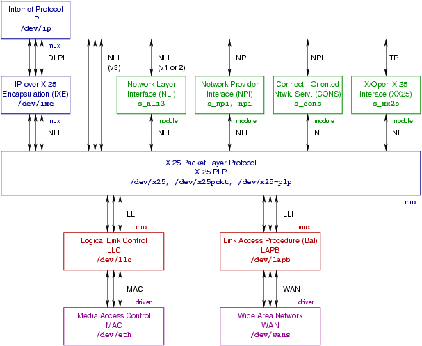
Figure C-1 illustrates the STREAMS multiplexing drivers, pseudo-device drivers, and pushable modules, and their organization.
C.1 NLI Multiplexing Driver
The NLI STREAMS multiplexing driver implements the X.25 Packet Layer Protocol (PLP) and provides the Network Layer Interface (NLI), Version 3, at it upper multiplex. Data links are linked beneath the driver at the lower multiplex. Linked Streams under OpenSS7 X.25 Networking conform to the Data Link Provider Interface (DLPI),76 however, implemetnations based on SpiderX.25 might use some other interface at this level.77
Each Stream on the upper multiplex of the NLI multiplexing driver represents either a VC or a PVC. Each Stream on the lower multiplex of the NLI multiplexing driver represents a data link78 or subnetwork79 interface.80
Many Spider-based implementations of X.25 will call this multiplexing driver simply /dev/x25. AIXlink/X.25 calls the driver /dev/x25pckt.
The STREAMS /dev/x25-plp multiplexing pseudo-device driver is illustrated in Figure C-1.
C.2 NLI Conversion Module
Many Spider-based implementations of X.25 will call this multiplexing driver s_nli3.
The STREAMS s_nli3 pushable module is illustrated in Figure C-1.
C.3 NPI Conversion Module
Many Spider-based implementations of X.25 will call this pushable module s_npi. AIXlink/X.25 calls the module npi.
The STREAMS s_npi and npi pushable modules are illustrated in Figure C-1.
C.4 CONS Module
The STREAMS s_cons pushable module is illustrated in Figure C-1. 81
C.5 XX25 Module
The STREAMS s_xx25 pushable module is illustrated in Figure C-1.
C.6 IXE Multiplexing Driver
The IXE module provides Internet Protocol over X.25 Encapsulation (IXE) per
RFC 877 and RFC 1356. The protocol module provides an DL_IPX25 MAC
type DLPI Stream on the upper multiplex and a NLI Stream (or possibly an
NPI Stream) on the lower multiplex. Each lower multiplex Stream
represents an X.25 PVC or VC. Each upper multiiplex Stream represents a
DL_IPX25 connectionless data link Stream.
The STREAMS /dev/ixe multiplexing driver is illustrated in Figure C-1.
C.7 IP Multiplexing Driver
The STREAMS /dev/ip multiplexing pseudo-device driver is illustrated in Figure C-1.
Appendix D NLI Utilities
Most implementations of the NLI provides a number of utilities that are aimed at providing three or four capabilities as follows:
- Adjusting the tunable parameters associated with X.25 subnetwork attachments.
- Administating mapping data for PVC and NUI.
- Collecting and displaying statistics.
- Monitoring traffic flow on specific VCs.
nuimap(8) | Adjust the Network User Identity mapping in the X.25 packet layer.
|
pvcmap(8) | Adjust the Permanent Virtual Circuit (PVC) mapping in the X.25 packet layer.
|
vcstat(8) | Collect virtual circuit (VC) statistics from the X.25 packet layer.
|
x25diags(8) | Convert X.25 diagnostics to messages and visa versa.
|
x25file(8) | -
|
x25info(8) | -
|
x25netd(8) | The X.25 network daemon.
|
x25route(8) | -
|
x25stat(8) | Collect subnetwork and global X.25 statistics from the X.25 packet layer.
|
x25trace(8) | Provide tracing on X.25 subnetworks.
|
x25tune(8) | Adjust the tunable parameters associated with a subnetwork to the X.25 packet layer.
|
D.1 nuimap - NUI mapping utility
The Network User Identity (NUI) mapping utility is responsible for administration of the mapping of NUI values to the facilities that are associated with a specific user value. The nuimap capability is invoked when the call indicates that subcription to NUI override facility is available and specifies a NUI for override. In this case, the NUI mapping table is consulted to look up the specified NUI and determine the facilities to override.
This utility is also described in the manual pages nuimap(8) and
nuimapconf(5). In this manual, see also NUI Mapping File.
Name
nuimap – NUI mapping utility
Synopsis
     nuimap [options] [-G] -n netuid [-d device]
     nuimap [options]  -D  -n netuid [-d device]
     nuimap [options]  -M  [-d device] [-f filename]
     nuimap [options]  -P  [-d device] [-f filename]
     nuimap [options]  -Z  [-d device]
     nuimap {-h|--help}
     nuimap {-V|--version}
     nuimap {-C|--copying}
Description
X.25 Packet Layer Protocol drivers supporting the NLI provide a mechanism for mapping Network User Identities to a set of X.25 facilities that are subscribed by the Network User Identity. nuimap provides a mechanism whereby the user can modify these mappings, or system configuration scripts can load or dump mappings to or from a file.
Facilities that can be subscribed on a network user basis are:
- Extended format packets.
- Local and remote packet sizes.
- Local and remote window sizes.
- Local and remote throughput classes.
- Subscription to closed user groups.
- Subscription to closed user groups with outgoing access.
- Subscription to basic format closed user groups.
- Subscription to extended format closed user groups.
The nuimap command can be used to retrieve or delete a specific network user identity to facilities mapping (-G or -D options, resp.); list or remove all network user identity to facilities mappings (-M or -Z options); or load a set of network user identity to facilities mappings from a file (-P option).
These capabilities of the nuimap command are supported by the
N_nuimsg, N_nuiput, N_nuidel, N_nuiget,
N_nuimget and N_nuireset input-output controls, see NUI_MSG Input-Output Controls.
See NUI Mapping File, for more information on supported facilities.
Options
The nuimap command accepts the following options:
Command Options
The following command options are mutually exclusive (except for -h, -V and -C which never cause an error when specified with another command option). If no command option is given, -G is assumed.
- -G, --get
- Get the network user identity to facilities mapping belonging to the NUI having
the same value as the argument to the -n option, netuid, for the
specified or default device.
The -n option and option argument, netuid, must be specified.
- -D, --delete
- Delete the network user identity to facilities mapping belonging to the NUI
having the same value as the argument to the -n option, netuid,
for the specified or default device.
The -n option and option argument, netuid, must be specified.
- -M, --list
- List all the network user identity to facilities mappings for the specified or
default device, and print them to stdout (or filename, when
specified with the -f option), for the specified or default
device.
- -P, --load
- Load a set of network user identity to facilities mappings for the specified or
default device, taking input from
/etc/sysconfig/strx25/nuimapconf (or filename,
when specified with the -f option), for the specified or default
device.84
- -Z, --reset
- Reset all network user identity to facilities mappings for the specified or
default device.
- -h, --help
- When this option is encountered, usage information is printed to stdout,
option processing stops, and the program exists successfully without taking any
further action.
- -V, --version
- When this option is encountered, version information is printed to
stdout, option processing stops, and the program exits successfully
without taking any further action.
- -C, --copying
- When this option is encountered, copying permissions are printed to stdout, option processing stops, and the program exits successfully without taking any further action.
Non-Command Options
The following non-command options cab be combined together and with any command option. Non-command options that are not necessary for the specified command option do not generate an error by mere combination.
- -f, --file filename
- Specifies the filename from which to read (-P option) or write
(-M option) configuration information.
This option and argument is optional. When the filename is not given and the -P option is specified, the values are read from /etc/sysconfig/strx25/nuimapconf;85 for the -M option, values are written to stdout.
If the filename is an absolute path (i.e. begins with ‘/’), then filename is assumed to be the exact path specified. Otherwise, the file required is assumed to be /etc/sysconfig/strx25/filename.86 See NUI Mapping File, for the format of the file.
- -n, --nui netuid
- Specifies the specific Network User Identity, netnuid, that identifies a
specific network user identity to faciltiies mapping to either be retrieved
(option -G) or deleted (option -D). This option must be
provided when the -G or -D command options are specified.
- -d, --device devname
- Specifies the device, devname, to open when tuning. When unspecified,
the default is /dev/x25. See also Devices, below.
- --dryrun
- Execute the command (-G, -D, -M or -P) as a
dry run. When this option is specified with the -D or -P
option, the input is read and checked for validity, but the configuration is not
written to the device when specified with the -G or -M option,
information is read from the device, but configuration information is not
output. The exit status and diagnostic output of the command still reflects the
success or failure of the command.
- -q, --quiet
- Suppresses normal output. This is the same as ‘--verbose=0’.
- --debug [level]
- Increase or specify the debug verbosity level. The default debug
level is zero (0). This option may be repeated. Level zero (0)
corresponds to no debugging output.
- -v, --verbose [level]
- Increase or specify the output verbosity level. The default output level is one (1). This option may be repeated. Level zero (0) corresponds to no normal output.
Diagnostics
An exit status of zero (0) indicates that the command was successful; one (1) indicates that an error occured and a diagnostic message is printed to stderr; two (2) indicates that the option or argument syntax was in error and a diagnostic message is printed to stderr.
The --quiet option suppresses the printing of normal output to stdout and diagnostic messages to stderr.
File Format
For the input file format, see NUI Mapping File.
Notices
On input, this implementation will handle fields that are separated by any whitespace (any number of blanks, horzontal tabs, new lines, carriage returns, vertical tabs, form feeds). On output, newlines are generated after fields.
Devices
- /dev/streams/clone/x25
- /dev/x25
- The NPI device for X.25,
x25(4).
Files
- /etc/sysconfig/strx25/filename
- The default directory location for configuration files used by this
command.87
- /etc/sysconfig/strx25/nuimapconf
- The default configuration file from which to read network user identity to facilities mappings for use with the -P option.
Bugs
nuimap has no known bugs.
See Also
Compatibility
The nuimap command is compatible with Spider X.25, and implementations based on Spider X.25, such as AIXlink/X.25, HP-UX, IRIS SX.25, PT X.25, RadiSys WAN, SBE X.25, Solstice X.25, and others, with the following portability considerations:
- A version of this command is provided by OpenSS7 X.25 Networking for
compatibility with systems that require it. Neither this command nor the
xnetd(8)are recommended for configuration of the OpenSS7 X.25 Networking subsystems. Use the SNMP agent instead. - Options -e, -n, -q, -v, -h, -V, -C, and all long options, are specific to this OpenSS7 X.25 Networking implementation of nuimap and will not be used by portable command scripts.
- No other implementation documents printing the output to a file when a filename is specified with the -G command option. This is an enhancement of this implementation.
- No other implementation documents the -e, -n, -q, -v, -h, -V, and -C, options. They will not be used by portable command scripts.
- Options --help and --version are provided for compatibility with GNU coding standards (GNITS); --copying, OpenSS7 coding standards.
For additional compatibilty considerations, see NLI Compatibility and Porting.
Conformance
AIXlink/X.25, HP-UX, IRIS SX.25, PT X.25, RadiSys WAN, SBE X.25, Solstice X.25, documentation. See References.
History
nuimap first appeared in Spider X.25.
D.2 pvcmap - PVC mapping utility
The Permanent Virtual Circuit (PVC) mapping utility is responsible for administration of the mapping of PVC logical channel identifiers to the facilities that are associated with a specific channel that would normally be negotiated on call setup. These include: local and remote packet and window sizes.
This utility is also described in the manual pages pvcmap(8) and
pvcmapconf(5). In this manual, see also PVC Mapping File.
Name
pvcmap – PVC mapping utility
Synopsis
     nuimap [options]  -G  [-s subnet] [-l lci] [-d device]
     nuimap [options]  -D  [-s subnet] [-l lci] [-d device]
     nuimap [options] [-M] [-d device] [-f filename]
     nuimap [options]  -P  [-d device] [-f filename]
     nuimap [options]  -Z  [-d device]
     nuimap {-h|--help}
     nuimap {-V|--version}
     nuimap {-C|--copying}
Description
X.25 Packet Layer Protocol drivers upporting the NLI provide a mechanism for attaching Permanent Virtual Circuits (PVC) for use by upper layer protocols. pvcmap provides a mechanism whereby the administrator can modify the local and remote packet and window sizes associated with PVC for each logical channel and subnetwork. For each PVC logical channel on each subnetwork, the following is specified:
- Local maximum packet size.
- Remote maximum packet size.
- Local maximum window size.
- Remote maximum window size.
The pvcmap command can be used to retrieve or delete the throughput parameters specific to a logical channel within a subnetwork (-G or -D options, resp.); list or remove all subnetwork and logical channel mappings (-M or -Z options); or load a set of subnetwork and logical channel mappings from a file (-P option).
The capabilities of the pvcmap command are supported by the
N_putpvcmap and N_getpvcmap intput-output controls,88 and provide an excellent example of
their use.
See PVC Mapping File, for more information on supported facilities.
Options
The pvcmap command accepts the following options:
Command Options
The following command options are mutually exclusive (except for -h, -V and -C which never cause an error when specified with another command option). If no command option is given, -G is assumed.
- -G, --get
- Get the subnetwork and logical channel mapping belonging to the subnet
having the same value as the argument to the -s option, and an
lci the same value as the argument to the -l option, when
provided, for the specified or default device.
The -s option and option argument, subnet, must be specified.
- -D, --delete
- Get the subnetwork and logical channel mapping belonging to the subnet
having the same value as the argument to the -s option, and an
lci the same value as the argument to the -l option, when
provided, for the specified or default device.
The -s option and option argument, subnet, must be specified.
- -M, --list
- List all the subnetwork and logical channel mappings for the specified or
default device, and print them to stdout (or filename, when
specified with the -f option), for the specified or default
device.
- -P, --load
- Load a set of subnetwork and logical channel PVC mappings for the specified or
default device, taking input from
/etc/sysconfig/strx25/pvcmapconf (or filename,
when specified with the -f option), for the specified or default
device.89
- -Z, --reset
- Reset all subnetwork and logical channel PVC mappings for the specified or
default device.
- -h, --help
- When this option is encountered, usage information is printed to stdout,
option processing stops, and the program exists successfully without taking any
further action.
- -V, --version
- When this option is encountered, version information is printed to
stdout, option processing stops, and the program exits successfully
without taking any further action.
- -C, --copying
- When this option is encountered, copying permissions are printed to stdout, option processing stops, and the program exits successfully without taking any further action.
Non-Command Options
The following non-command options cab be combined together and with any command option. Non-command options that are not necessary for the specified command option do not generate an error by mere combination.
- -f, --file filename
- Specifies the filename from which to read (-P option) or write
(-M option) configuration information.
This option and argument is optional. When the filename is not given and the -P option is specified, the values are read from /etc/sysconfig/strx25/pvcmapconf;90 for the -M option, values are written to stdout.
If the filename is an absolute path (i.e. begins with ‘/’), then filename is assumed to be the exact path specified. Otherwise, the file required is assumed to be /etc/sysconfig/strx25/filename.91 See PVC Mapping File, for the format of the file.
- -s, --subnet subnet
- Specifies the subnetwork identifier, subnet, to which the PVC is attached.
subnet is normally an alphabetical character starting at ‘A’ for the
first subnetwork, ‘B’ for the second subnetwork, and so on. When not
given, all subnetworks are assumed.
- -l, --lci lci
- Specifies the logical channel identifier lci, to which the PVC
corresponds. lci is normally an interger value between 1 and 4096. Zero
(0) is not permitted. When not specified, any and all logical channels are
assumed.
- -d, --device devname
- Specifies the device, devname, to open when mapping. When unspecified,
the default is /dev/x25. See also Devices, below.
- -n, --dryrun
- Execute the command (-G, -D, -M or -P) as a
dry run. When this option is specified with the -D or -P
option, the input is read and checked for validity, but the configuration is not
written to the device when specified with the -G or -M option,
information is read from the device, but configuration information is not
output. The exit status and diagnostic output of the command still reflects the
success or failure of the command.
- -q, --quiet
- Suppresses normal output. This is the same as ‘--verbose=0’.
- --debug [level]
- Increase or specify the debug verbosity level. The default debug
level is zero (0). This option may be repeated. Level zero (0)
corresponds to no debugging output.
- -v, --verbose [level]
- Increase or specify the output verbosity level. The default output level is one (1). This option may be repeated. Level zero (0) corresponds to no normal output.
Diagnostics
An exit status of zero (0) indicates that the command was successful; one (1) indicates that an error occured and a diagnostic message is printed to stderr; two (2) indicates that the option or argument syntax was in error and a diagnostic message is printed to stderr.
The --quiet option suppresses the printing of normal output to stdout and diagnostic messages to stderr.
File Format
For the input file format, see PVC Mapping File.
Notices
On input, this implementation will handle fields that are separated by any whitespace (any number of blanks, horzontal tabs, new lines, carriage returns, vertical tabs, form feeds). On output, newlines are generated after fields.
Devices
- /dev/streams/clone/x25
- /dev/x25
- The NPI device for X.25,
x25(4).
Files
- /etc/sysconfig/strx25/filename
- The default directory location for configuration files used by this
command.92
- /etc/sysconfig/strx25/pvcmapconf
- The default configuration file from which to read for subnetwork and logical channel PVC mappings for use with the -P option.
Bugs
pvcmap has no known bugs.
See Also
Compatibility
The nuimap command is compatible with Spider X.25, and implementations based on Spider X.25, such as AIXlink/X.25, HP-UX, IRIS SX.25, PT X.25, RadiSys WAN, SBE X.25, Solstice X.25, and others, with the following portability considerations:
- A version of this command is provided by OpenSS7 X.25 Networking for
compatibility with systems that require it. Neither this command nor the
xnetd(8)are recommended for configuration of the OpenSS7 X.25 Networking subsystems. Use the SNMP agent instead. - Options -e, -n, -q, -v, -h, -V, -C, and all long options, are specific to this OpenSS7 X.25 Networking implementation of nuimap and will not be used by portable command scripts.
- No other implementation documents printing the output to a file when a filename is specified with the -G command option. This is an enhancement of this implementation.
- No other implementation documents the -e, -n, -q, -v, -h, -V, and -C, options. They will not be used by portable command scripts.
- Options --help and --version are provided for compatibility with GNU coding standards (GNITS); --copying, OpenSS7 coding standards.
For additional compatibilty considerations, see NLI Compatibility and Porting.
Conformance
AIXlink/X.25, HP-UX, IRIS SX.25, PT X.25, RadiSys WAN, SBE X.25, Solstice X.25, documentation. See References.
History
pvcmap first appeared in Spider X.25.
D.3 vcstat - VC statistics utility
Name
Synopsis
Description
Options
Usage
Diagnostics
Notices
Bugs
See Also
Compatibility
Conformance
History
D.4 x25diags - X.25 diagnostics utility
Name
Synopsis
Description
Options
Usage
Diagnostics
Notices
Bugs
See Also
Compatibility
Conformance
History
D.5 x25file - X.25 file utility
Name
Synopsis
Description
Options
Usage
Diagnostics
Notices
Bugs
See Also
Compatibility
Conformance
History
D.6 x25info - X.25 information untility
Name
Synopsis
Description
Options
Usage
Diagnostics
Notices
Bugs
See Also
Compatibility
Conformance
History
D.7 x25netd - X.25 network daemon
Name
Synopsis
Description
Options
Usage
Diagnostics
Notices
Bugs
See Also
Compatibility
Conformance
History
D.8 x25route - X.25 routing control
Name
Synopsis
Description
Options
Usage
Diagnostics
Notices
Bugs
See Also
Compatibility
Conformance
History
D.9 x25stat - X.25 statistics utility
Name
Synopsis
Description
Options
Usage
Diagnostics
Notices
Bugs
See Also
Compatibility
Conformance
History
D.10 x25trace - X.25 trace utility
Name
Synopsis
Description
Options
Usage
Diagnostics
Notices
Bugs
See Also
Compatibility
Conformance
History
D.11 x25tune - X.25 tuning utility
Name
Synopsis
Description
Options
Usage
Diagnostics
Notices
Bugs
See Also
Compatibility
Conformance
History
Appendix E NLI File Formats
E.1 LAPB Template File
Name
lapbtemplate — Link Access Protocol (Balanced) File Format
Description
The lapbtemplate describes the file format for input to the
lltune(8) command for LAPB class subnetworks. The file format
consists of a number of parameter values, one per line, formatted as described
below. Each parameter value is described using its line number in the file, a
parameter name, and a description of the format of the value. Only the value
appears in the file, each value on a line by itself, one value per line.
Each of the LAPB configuration parameters correspons to the member and values
of the lapb_tune structure, that is carried in a lapb_tnioc
structure by the L_LAPBTUNE input-output control.
These protocol parameters, and the default values that exist when tuning has not been applied to a newly created LAPB subnetwork, correspond directly to the protocol parameters and defaults in ISO/IEC 7776, ITU-T Rec. X.25 and X.75.
Format
The LAPB template consists of 16 to 18 lines containing the following configuration information:
- N2_VAL is the maximum number of times that a protocol data unit (PDU) is set following the expiry of the acknowlegement timer, the P-bit timer, or the reject timer. It also limits the number of times an RR with the P-bit set is sent when remote busy is true and the busy timer expires.
- T1_VAL is the time during which the LAPB expects to receive an acknowledgement to an outstanding I-PDU or an expected response to a sent UI-PDU. The value is in units of 0.1 seconds (deciseconds).
- TPF_VAL is the time during which the LAPB expectes to receive a PDU with the F-bit set to 1 in response to a command with the P-bit set to 1. The value should be less than the acknowledgement timer. The value is in units of 0.1 seconds (deciseconds).
- TREJ_VAL is the time interval during which the LAPB expects to receive a reply to a sent REJ DPU. The value is in units of 0.1 seconds (deciseconds).
- TBUSY_VAL is the time interval during which the LAPB waits for an indication of the clearance of a busy condition at the other LAPB. The value is in units of 0.1 seconds (deciseconds).
- IDLE_VAL is the time interval during which the LAPB expects to receive a PDU from the other LAPB. If it expires then the P/F cycle is intiated which may result in link disconnection. The value is in units of 0.1 seconds (decicseconds).
- ACK_DELAY is the maximum delay in 0.1 second units before transmitting a delayed RR. This must be considerably less that the acknowledgement timer value, T1_VAL.
- NOTACK_MAX is the maximuum number of unacknowledged receive I PDUs before the RR acknowledging them all must be sent.
- LOC_WIND is the number of unacknowledged I PDUs that may be sent.
- LOC_PROBE is the position before the window is closed at which an I PDU is sent with the P-bit set to solicit an acknowledgement from the receiver.
- MAX_I_LEN is the maximum isze of a LAPB I-frame. LAPB requires all incoming I-frames above a certain size to be rejected by a FRMR. This parameter specifies the maximum size. It is constructured as the sum of the maximum X.25 data size, the X.25 protocol length and the LAPB protocol length.
- IGN_UA_ERROR define whether or not to ignore any UA frams received, when the connection is in ERROR state. The value is ‘1’ for true and ‘0’ for false. The defalt value is false.
- FRMR_FRMR_ERROR defines whether or not to re-transmit a frame
reject if a frame reject is received, when the connection is in
ERRORstate. The value is ‘1’ for true and ‘0’ for false. The default value is false. - FRMR_INVRSP_ERROR defines whether or not to transmit a frame
reject if an invalid frame response is received, when the connection is in
ERRORstate. The value is ‘1’ for true and ‘0’ for false. The default value is false. - SFRAME_PBIT defines whether or not to send a frame reject if an S-frame is received without the P-bit set. The value is ‘1’ for truea nd ‘0’ for false. The default value is false.
- NO_DM_ADM defines whether or not to send a
DMon entry toADMstate after an N2 count expiry. The value is ‘1’ for true and ‘0’ for false. The default value is false.
The following two fields are optional extensions:
- IGN_DM_ERROR defines whether or not to ignore DM frames received,
when the connection is in
ERRORstate. The value is ‘1’ for true and ‘0’ for false. The default value is false. - SABM_IN_X32 defines the action to take when a SABM is received in X.32 setup. The value is ‘1’ for true and ‘0’ for false. The default value is false.
The last two fields (‘17’ and ‘18’) are enhancements.
Files
Files following this format are normally kept in the /etc/sysconfig/strx25/template/ directory.93
See Also
Compatibility
The lapbtemplate file format is compatible with Spider X.25, and implementations based on Spider X.25, such as AIXlink/X.25, HP-UX, IRIS SX.25, Solstice X.25, PT X.25, SBE X.25, with the following compatibility considerations:
- Most implementations only define the first 16 lines. This implementation defines 18 lines, where the first 16 lines are compatible with other implementations and the last additional two lines are optional.
- PT X.25 documents the SABM_IN_X32 LAPB template field but not the IGN_DM_ERROR LAPB template field. Solstice X.25 and IRIS SX.25 do not document either the IGN_DM_ERROR nor SABM_IN_X32 LAPB template fields.
For additional compatiblity infromation see, lapb(4), and
STREAMS(9).
Conformance
AIXlink/X.25, HP-UX, IRIS SX.25, Solstice X.25, PT X.25, SBE X.25, documentation.
History
The lapbtemplate file format first appeared in Spider X.25.
E.2 LLC2 Template File
Name
llc2template — Logical Link Control Type 2 File Format
Description
The llc2template describes the file format for input to the
lltune(8) command for LLC2 class subnetworks. The file format
consists of a number of parameter values, one per line, formatted as described
below. Each parameter value is described using its line number in the file, a
parameter name, and a description of the format of the value. Only the value
appears in the file, each value on a line by itself, one value per line.
Each of the LLC2 configuration parameters corresponds to the member and values
of the llc2_tune structure, that is carried in a llc2_tnioc
structure by the L_LLC2TUNE input-output control.
These protocol parameters, and the default values that exist when tuning has not been applied to a newly created LLC2 subnetwork, correspond directly to the protocol parameters and defaults in ISO/IEC 8802-2:1998.
Format
The LLC2 template consists of 14 lines containing the following configuration information.
- N2_VAL is the maximum number of times that a Protocol Data Unit (PDU) is sent following the expiry of the acknowledgement timer, the P-bit timer, or the reject timer. This parameter also limits the number of times an RR is sent with the P-bit set when remote busy is true and the busy timer expires.
- T1_VAL is the time interval during which the LLC2 expects to receive an acknowledgement to an outstanding I-PDU or an expected response to a sent UI-PDU. The value is in units of 0.1 seconds.
- TPF_VAL is the time during which the LLC2 expects to receive a PDU with the F-bit set to 1 in response to a command with the P-bit set to 1. The value should be less than that specified for the akcnowledgement timer. The value is in units of 0.1 seconds.
- TREJ_VAL is the time interval during which the LLC2 expects to receive a reply to a sent REJ PDU. The value is in units of 0.1 seconds.
- TBUSY_VAL is the timer interval during which the LLC2 waits for an indication of the clearance of busy condition at the other LLC2. The value is in units of 0.1 seconds.
- TIDLE_VAL is the time interval during which the LLC2 expects to receive a PDU from the other LLC2. The value is in units of 0.1 seconds.
- ACK_DELAY is the RR delay time. This is the time interval for which the LLC2 will withhold acknowledgements of unacknowledged received I-PDUs. The value is in units of 0.1 seconds.
- NOTACK_MAX is the maximum number of unacknowledged received I-frames.
- TX_WINDOW is the transmit window (if no XID received).
- TX_PROBE is the position before the window is closed at which an I-PDU is sent with the P-bit set to solicit an acknowledgement from the receiver.
- MAX_I_LEN
is the maximum size of an LLC2 I-frame. LLC2 requires all incoming I-frames
above a certain size to be rejected by a FRMR. This parameter specifies the
maximum size of data that may bereceived starint from the LLC2 protocol header.
In an X.25 network, it is constructed as (maximum X.25 data length + X.25 protool header length + LLC2 protocol header length). In an SNA network, it is constructed as (maximum SNA data length + SNA request header length + SNA transmission header length + LLC2 protocol header length).
- XID_WINDOW is the XID window size (receive window), when the remote window size is unknown or zero.
- XID_NDUP is the duplicate MAC XID count (0 means no test).
- XID_TDUP is the duplicate MAC XID time. The value is in units of 0.1 seconds.
Files
Files following this format are normally kept in the /etc/sysconfig/strx25/template/ directory.94
See Also
Compatibility
The llc2template file format is compatible with Spider X.25, and implementations based on Spider X.25, such as AIXlink/X.25, HP-UX, IRIS SX.25, Solstice X.25, PT X.25, SBE X.25, with the following compatibility considerations:
- PT X.25 does not support LLC2. OpenSS7 X.25 Networking supports LLC2 in support of XOL and porting applications from AIXlink/X.25, Solstice X.25, HP-UX, IRIS SX.25, VxWorks, pSOS, SpiderX, and many other implementations based on SpiderX.25 support LLC2. Portable X.25 and XOL applications will use OpenSS7 X.25 Networking instead of PT X.25.
llc2(4), and
STREAMS(9).
Conformance
AIXlink/X.25, HP-UX, IRIS SX.25, Solstice X.25, PT X.25, SBE X.25, documentation.
History
The llc2template file format first appeared in Spider X.25.
E.3 NUI Mapping File
Name
Description
Format
Files
See Also
Compatibility
History
E.4 PAD Entries File
Name
Description
Format
Files
See Also
Compatibility
History
E.5 X.25 Template File
Name
x25template — X.25 Subnetwork File Format
Description
The x25template describes the file format for input to the
x25tune(8) command for X.25 subnetworks. The file format consists of
a number of parameter values, one per line, formated as described below. Each
parameter value is described using its line number in the file, a parameter
name, and a description of the format of the value. Only the value appears in
the file, each value on a line by itself, one value per line.
Each of the X.25 configuration parameters corresponds to the member and values
of the wlcfg structure by the N_snconfig and N_snread
input-output controls.
.
These protocol parameters, and the default values that exist when tuning has
not been applied to a newly created X.25 subnetwork, correspond directly to the
protocol parameters and defaults in ISO/IEC 8208 , ITU-T Rec.
X.25 and X.75.
Format
The X.25 subnetwork template consists of 76 or more lines containing the following configuration information:
- NET_MODE
determines the various characteristics of the network protocol. Valid values
are integers, as specified below, that refers to the networks listed:
1 - X25_LLC 10 - TRANSPAC 19 - DCS 2 - X25_88 11 - TYMNET 20 - TELEPAC 3 - X25_84 12 - DATEX_P 21 - F_DATAPAC 4 - X25_80 13 - DDX_P 22 - FINPAC 5 - PSS 14 - VENUS_P 23 - PACNET 6 - AUSTPAC 15 - ACCUNET 24 - LUXPAC 7 - DATAPAC 16 - ITAPAC 25 - X25_CIRCUIT 8 - DDN 17 - DATAPAK 9 - TELENET 18 - DATANET - X25_VERSION
determines the version of the X.25 protocol that is being used over the
network. Valid values are integers, as specified below. Note that a
NET_MODE of X25_LLC will override any value in this field to 1984
(or later).
80 - indicates 1980 84 - indicates 1984 88 - indicates 1988 1980 - indicates 1980 1984 - indicates 1984 1988 - indicates 1988 1992 - indicates 1992 1996 - indicates 1996 2000 - indicates 2000 2004 - indicates 2004 YYYY - indicates YYYY - L3PLPMODE
indicates the DTE/DCE nature of the link. Valid value are integers, as
specified below. Note that DXE operation is per ISO
8208.95
0 - indicates DCE 1 - indicates DTE 2 - indicates DXE - LPC is the lowest LCI for Permanent Virtual Circuits (PVC). LPC and HPC define the range of LCI that are assigned to PVC. This range cannot overlap with the other defined ranges. Setting this value to zero and HPC to zero specifies that there are no PVC. Valid values contain 3 hexadecimal digits ‘000’ through ‘FFF’. Leading zeros are optional.
- HPC is the highest LCI for PVC. LPC and HPC define the range of LCI that are assigned to PVC. This range cannot overlap with the other defined ranges. LPC and HPC set to zero means no PVC. Valid values contain 3 hexadecimal digits ‘000’ through ‘FFF’. Leading zeros are optional.
- LIC is the lowest incoming (IC) VC. LIC and HIC define the range of LCI that are assigned to incoming call circuits. This range cannot overlap with the other defined ranges. LIC and HIC zero means no IC VC. Use 3 hexadecimal digits ‘000’ through ‘FFF’. Leading zeros are optional.
- HIC is the highest IC VC. LIC and HIC define the range of LCI that are assigned to incoming call circuits. This range cannot overlap. LIC and HIC zero means no IC VC. Use 3 hexadecimal digits ‘000’ through ‘FFF’. Leading zeros are optional.
- LTC is the lowest two-way (TW) VC. LTC and HTC define the LCI that are assigned to two-way call circuits. This range cannot overlap. LTC and HTC zero means no TW VC. Use 3 hexadecimal digits ‘000’ through ‘FFF’. Leading zeros are optional.
- HTC is the highest TW VC. LTC and HTC define the LCI that are assigned to two-way call circuits. This range cannot overlap. LTC and HTC zero means no TW VC. Use 3 hexadecimal digits ‘000’ through ‘FFF’. Leading zeros are optional. j
- LOC is the lowest outgoing (OG) VC. LOC and HOC define the range assigned to outgoing call circuits. This range cannot overlap. LOC and HOC zero means no OG VC. Use 3 hexadecimal digits ‘000’ through ‘FFF’. Leading zeros are optional.
- HOC is the highest OG VC. LOC and HOC define the range assigned to outgoing call circuits. This range cannot overlap. LOC and HOC zero means no OG VC. Use 3 hexadecimal digits ‘000’ through ‘FFF’. Leading zeros are optional. j
- THISGFI
indicates which Modulo operates on the network. It can have one of three
integer values.
8 - Modulo 8 3 bits 128 - Modulo 128 7 bits 32768 - Modulo 32768 15 bits 2147483648 - Modulo 2147483648 31 bits - LOCMAXPKTSIZE
is the maximum acceptable packet size for sent packets.
The value is the logarithm, base two, of the packet size. Valid values are in
the range from 7 to 12, signifying a size of 128 to 4096 in powers of two.
The default value is 7 (or 128 octets).
The local maximum packet size and remote maximum packet size should be the
same.
The value should be less than the maximum LAPB I-frame size, N2, see
lltune(8). - REMMAXPKTSIZE
is the maximum acceptable packet size for received packets.
The value is the logarithm, base two, of the packet size. Valid values are in
the range from 7 to 12, signifying a size of 128 to 4096 in powers of two.
The default value is 7 (or 128 octets).
The local maximum packet size and remote maximum packet size should be the
same.
The value should be less than the maximum LAPB I-frame size, N2, see
lltune(8). - LOCDEFPKTSIZE is the default packet size for sent packets. The value is the logarithm, base two, of the packet size. Valid values are in the range from 7 to 12, signifying a size of 128 to 4096 in powers of two. The local default packet size and remote maximum packet size should be the same. The default value is 7 (or 128 octets). When specified as 7 (128 octets), negotiation of the non-standard default packet size facility will neither be initiated nor rejected.
- REMDEFPKTSIZE is the default packet size for received packets. The value is the logarithm, base two, of the packet size. Valid values are in the range from 7 to 12, signifying a size of 128 to 4096 in powers of two. The local default packet size and remote maximum packet size should be the same. The default value is 7 (or 128 octets). When specified as 7 (128 octets), negotiation of the non-standard default packet size facility will neither be initiated nor rejected.
- LOCMAXWSIZE The value must be greater than one and less than the modulus value. The default value is 2 for Modulo 8 or Modulo 128; and 128 for Modulo 32768.
- REMMAXWSIZE The value must be greater than one and less than the modulus value. The default value is 2 for Modulo 8 or Modulo 128; and 128 for Modulo 32768.
- LOCDEFWSIZE The value must be greater than one and less than the modulus value. The default value is 2 for Modulo 8 or Modulo 128; and 128 for Modulo 32768. When specified as 2 for Modulo 8 or Modulo 128, or 128 for Modulo 32768, the non-standard default window size facility will neither be initiated nor rejected.
- REMDEFWSIZE The value must be greater than one and less than the modulus value. The default value is 2 for Modulo 8 or Modulo 128; and 128 for Modulo 32768. When specified as 2 for Modulo 8 or Modulo 128, or 128 for Modulo 32768, the non-standard default window size facility will neither be initiated nor rejected.
- MAXNSDULEN
- ACKDELAY
- T20VALUE
(Restart Request Response Timer)
is the time period that the DTE will await a restart confirmation or restart
indication following issuing a request request.
The timeout value should not be less than 180 seconds.
The value is in integral units of deciseconds (0.1 seconds), so an interval of
180 seconds is specified as 1800 (deciseconds).
T10VALUE (Restart Indication Response Timer) is the equivalient timer for the DCE, and defines the time period that the DCE will wait for a restart confirmation or restart request after having issued a restart indication. The timeout value is a minimum of 60 seconds. The value is in integral units of deciseconds (0.1 seconds), so an interval of 60 seconds is specified as 600 (deciseconds).
- T21VALUE
(Call Request Response Timer)
is the time period that the DTE will await a call connected or clear
indication having issued a call request.
The timeout value should not be less than 200 seconds.
The value is in integral units of deciseconds (0.1 seconds), so an interval of
200 seconds is specified as 2000 (deciseconds).
T11VALUE (Incoming Call Response Timer) is the equivalent timer for the DCE, and defines the time period that the DCE will wait for a call accepted, clear request or call request after having issued an incoming call. The timeout value is a minimum of 180 seconds. The timeout value is a minimum of 60 seconds. The value is in integral units of deciseconds (0.1 seconds), so an interval of 180 seconds is specified as 1800 (deciseconds).
- T22VALUE
(Reset Request Response Timer)
is the time period that the DTE will await a reset confirmation or reset
indication having issued a reset request.
The timeout value should not be less than 180 seconds.
The value is in integral units of deciseconds (0.1 seconds), so an interval of
180 seconds is specified as 1800 (deciseconds).
T12VALUE (Reset Indication Response Timer) is the equivalent timer for the DCE, and defines the time period that the DCE will wait for a reset confirmation or request request after having issued a reset indication. The timeout value is a minimum of 60 seconds. The timeout value is a minimum of 60 seconds. The value is in integral units of deciseconds (0.1 seconds), so an interval of 60 seconds is specified as 600 (deciseconds).
- T23VALUE
(Clear Request Response Timer)
is the time period that the DTE will await a clear confirmation or clear
indication having issued a clear request.
The timeout value should not be less than 180 seconds.
The value is in integral units of deciseconds (0.1 seconds), so an interval of
180 seconds is specified as 1800 (deciseconds).
T13VALUE (Clear Indication Response Timer) is the equivalent timer for the DCE, and defines the time period that the DCE will wait for a clear confirmation or clear request following issuing a clear indication. The timeout value is a minimum of 60 seconds. The value is in integral units of deciseconds (0.1 seconds), so an interval of 60 seconds is specified as 600 (deciseconds).
- TVALUE
- T25VALUE
(Window Rotation Timer)
is the time period that the DTE will await acknowledgement of all outstanding
data packets having trasnmitted the last available data packet or the window
is rotated.
The timeout value should not be less than 200 seconds.
The value is in integral units of deciseconds (0.1 seconds), so an interval of
200 seconds is specified as 2000 (deciseconds).
Note that this T25 timer is only needed if the associated procedure96 is used.
- T26VALUE (Interrupt Response Timer) is the time period that the DTE will await an interrupt confirmation having issued an interrupt. The timeout value should not be less than 180 seconds. The value is in integral units of deciseconds (0.1 seconds), so an interval of 180 seconds is specified as 1800 (deciseconds).
- IDLEVALUE
- CONNECTVALUE
- R20VALUE (Restart Request Retransmission Count) is the number of times that a restart request will be re-issued, and T20 restarted, upon expiry of timer T20. This value has a default of 1 and a minimum of 1.
- R22VALUE (Reset Request Retransmission Count) is the number of times that a reset request will be re-issued, and T22 restarted, upon expiry of timer T22. This value has a default of 1 and a minimum of 1.
- R23VALUE (Clear Request Retransmission Count) is the number of times that a clear request will be re-issued, and T23 retstarted, upon expiry of timer T23. This value has a default of 1 and a minimum of 1.
- LOCALDELAY
- ACCESSDELAY
- LOCMAXTHCLASS
is the local maximum throughput class.
The value is an integer number from 3 to 44.
Basic ISO 8208 throughput classes can have a value from 3 to 16, corresponding to throughputs between 75 and 192,000 bits/s, listed in Table 20a of ISO/IEC 8208:2000, or Extended ISO 8208 throughput classes can have a value from 3 through 44, corresponding to throughputs between 75 and 2,048,000 bits/s, listed in Table 20b of ISO/EIC 8208:2000.97
- REMMAXTHCLASS
is the remote maximum throughput class.
The value is an integer number from 3 to 44.
Basic ISO 8208 throughput classes can have a value from 3 to 16, corresponding to throughputs between 75 and 192,000 bits/s, listed in Table 20a of ISO/IEC 8208:2000, or Extended ISO 8208 throughput classes can have a value from 3 through 44, corresponding to throughputs between 75 and 2,048,000 bits/s, listed in Table 20b of ISO/EIC 8208:2000.98
- LOCDEFTHCLASS
is the local default throughput class.
The value is an integer number from 3 to 44.
Basic ISO 8208 throughput classes can have a value from 3 to 16, corresponding to throughputs between 75 and 192,000 bits/s, listed in Table 20a of ISO/IEC 8208:2000, or Extended ISO 8208 throughput classes can have a value from 3 through 44, corresponding to throughputs between 75 and 2,048,000 bits/s, listed in Table 20b of ISO/EIC 8208:2000.99
- REMDEFTHCLASS
is the remote default throughput class.
The value is an integer number from 3 to 44.
Basic ISO 8208 throughput classes can have a value from 3 to 16, corresponding to throughputs between 75 and 192,000 bits/s, listed in Table 20a of ISO/IEC 8208:2000, or Extended ISO 8208 throughput classes can have a value from 3 through 44, corresponding to throughputs between 75 and 2,048,000 bits/s, listed in Table 20b of ISO/EIC 8208:2000.100
- LOCMINTHCLASS
is the local minimum throughput class.
The value is an integer number from 3 to 44.
Basic ISO 8208 throughput classes can have a value from 3 to 16, corresponding to throughputs between 75 and 192,000 bits/s, listed in Table 20a of ISO/IEC 8208:2000, or Extended ISO 8208 throughput classes can have a value from 3 through 44, corresponding to throughputs between 75 and 2,048,000 bits/s, listed in Table 20b of ISO/EIC 8208:2000.101
- REMMINTHCLASS
is the remote minimum throughput class.
The value is an integer number from 3 to 44.
Basic ISO 8208 throughput classes can have a value from 3 to 16, corresponding to throughputs between 75 and 192,000 bits/s, listed in Table 20a of ISO/IEC 8208:2000, or Extended ISO 8208 throughput classes can have a value from 3 through 44, corresponding to throughputs between 75 and 2,048,000 bits/s, listed in Table 20b of ISO/EIC 8208:2000.102
- SUB_CUG (Closed User Group) is the index to the closed user group selected for the virtual call in the form of two to four decimal digits. Indexes to the close user group at different DXE interfaces may be different. The value is ‘Y’ for use and ‘N’ for non-use.
- SUB_PREF (Preferential Closed User Group). When the DTE belongs to more than one closed user group, a preferential closed user group must be specified. The value is ‘Y’ for use and ‘N’ for non-use.
- SUB_CUGOA (Closed User Group with Outgoing Access) is the index to the closed user group selected for the virtual call in the form of two to four decimal digits. Indexes to the close user group at different DXE interfaces may be different. The value is ‘Y’ for use and ‘N’ for non-use.
- SUB_CUGIA (Closed User Group with Incoming Access) is the index to the closed user group selected for the virtual call in the form of two to four decimal digits. Indexes to the close user group at different DXE interfaces may be different. The value is ‘Y’ for use and ‘N’ for non-use.
- CUG_FORMAT (Number of Closed User Groups Subscribed) defines the maximum number of closed user groups to which the DTE is subscribed. The value is in the range 0 to 100 for basic and in the range 101 to 10000 for extended. The value is ‘Y’ for use and ‘N’ for non-use.
- BAR_CUG_IN (Closed User Group Incoming Calls Barred) is a user option that bars incoming calls containing the closed user group facility. The value is ‘Y’ for use and ‘N’ for non-use.
- SUB_EXTENDED (Extended Call Packets) The value is ‘Y’ for use and ‘N’ for non-use.
- BAR_EXTENDED (Extended Call Packets Barred) is a user option that bars incoming calls containing flow control negotiation facilities. The value is ‘Y’ for use and ‘N’ for non-use.
- SUB_FSELECT (Fast Select Acceptance) is an optional user facility agreed for a period of time. This user facility, if subscribed to, authorizes the DCE to transmit to the DTE incoming calls that request the fast select facility. In the absence of this facility, the DCE will not transmit to the DTE incoming calls that request the fast select facility. This parameter defines whether the DTE accepts calls with a fast select facility requesting no restriction on response. The value is ‘Y’ for use and ‘N’ for non-use.
- SUB_FSRRESP (Fast Select Acceptance) is an optional user facility agreed for a period of time. This user facility, if subscribed to, authorizes the DCE to transmit to the DTE incoming calls that request the fast select facility. In the absence of this facility, the DCE will not transmit to the DTE incoming calls that request the fast select facility. This parameter defines whether the DTE accepts calls with a fast select facility requesting restriction on response. The value is ‘Y’ for use and ‘N’ for non-use.
- SUB_REVCHARGE (Reverse Charging Acceptance) is an optional user facility agree for a period of time for virtual calls. This user facility, if subscribed to, authorizes the DCE to transmit to the DTE incoming calls that request the reverse charging facility. In the absence of this facility, the DCE will not transmit to the DTE incoming calls that request the reverse charging facility. The value is ‘Y’ for use and ‘N’ for non-use.
- SUB_LOC_CHG_PREV (Local Charging Prevention) is an optional user faciltiy agreed for a period of time for virtual calls. This user facility, if subscribed to, authorizes the DCE to prevent the establishment of virtual calls that the suscriber must pay for by: a) not transmitting to the DTE incoming calls that request the reverse charging facility; and, b) ensuring that the charges are made to another party whether a call is requested by the DTE. When the party to be changed has not been established for a call request, the DCE that receives the call request packet will apply reverse charging to this call. The value is ‘Y’ for use and ‘N’ for non-use.
- BAR_INCALL (Incoming Calls Barred) determines whether the optional user facility is agreed for a period of time. This facility applies to all logical channels used at the DTE/DCE interface for virtual calls. This user facility, if subscribed to, prevents incoming virtual calls from being presented to the DTE. The DTE may originate outgoing virtual calls. Logical chanels used for virtual calls retain their full duplex capability. Some administratoins may provide a capability that allows a virtual call to be presented to the DTE only in cases where the called DTE address is the address of the calling DTE. The value is ‘Y’ for use and ‘N’ for non-use.
- BAR_OUTCALL (Outgoing Calls Barred) determines whether the optional user facilty is agreed for a period of time. This facility applies to all logical channels used at the DTE/DCE interface for virtual calls. This user facility, if subscribed to, prevents the DCE from accepting outgoing virtual calls from the DTE. The DTE may receive incoming virtual calls. Logical channels used for virtual calls retain their full duplex capability. The value is ‘Y’ for use and ‘N’ for non-use.
- SUB_TOA_NPI_FMT (TOA/NPI Address) is an optional user facility agreed for a period of time for virtual calls. When this facility is subscribed to, the DCE and DTE shall transmit call set-up and clearing packets only using the TOA/NPI address format. In this case, addresses in facilities are also in TOA/NPI format. The value is ‘Y’ for use and ‘N’ for non-use.
- BAR_TOA_NPI_FMT (TOA/NPI Address Incoming Calls Barred) is a user option that bars incoming calls containing TOA/NPI addresses. The value is ‘Y’ for use and ‘N’ for non-use.
- SUB_NUI_OVERRIDE (NUI Override) is an optional user facility agreed for a period of time for virtual calls. When this facility is subscribed to, one or more network user identifiers are also agreed for a period of time. Associated with each network user identifier is a set of subscription-time optional user facilities. When one of these network user identifiers is provdied in a call request packet by means of the NUI selection facility, the set of subscription-time optional user facilities associated with it overrides the facilities that apply to the interface. This override does not apply to other existing calls or subsequent calls on the interface. It remains in effect for the duration of the particular call to which it applies. The value is ‘Y’ for use and ‘N’ for non-use.
- ACC_NODIAG The value is ‘Y’ for use and ‘N’ for non-use.
- USE_DIAG The value is ‘Y’ for use and ‘N’ for non-use.
- CCITT_CLEAR_LEN The value is ‘Y’ for use and ‘N’ for non-use.
- BAR_DIAG The value is ‘Y’ for use and ‘N’ for non-use.
- DISC_NS_DIAG The value is ‘Y’ for use and ‘N’ for non-use.
- ACC_HEX_ADD The value is ‘Y’ for use and ‘N’ for non-use.
- BAR_NONPRIV_LISTEN The value is ‘Y’ for use and ‘N’ for non-use.
- INTL_ADDR_REGION
- INTL_PRIORITISED The value is ‘Y’ for use and ‘N’ for non-use.
- DNIC The value is 4 hexadecimal digits.
- PRTY_ENCODE_CONTROL The value is an integer decimal number.
- PRTY_PKT_FORCED_VAL The value is an integer decimal number.
- SRC_ADDR_CONTROL The value is an integer decimal number.
- DBIT_ACCEPT_IND
0 - leave the D-bit set and pass the packet on, 1 - zero the D-bit and pass the packet on, and, 2 - reset the call. - DBIT_ACCEPT_OUT
0 - leave the D-bit set and pass the packet on, 1 - zero the D-bit and pass the packet on, and, 2 - reset the call. - DBIT_DATA_IN
0 - leave the D-bit set and pass the packet on, 1 - zero the D-bit and pass the packet on, and, 2 - reset the call. - DBIT_DATA_OUT
defines the action to taken when the local user sends a data packet with the
D-bit set, but the remote party has not indicated D-bit support. It can have
one of the following values:
0 - leave the D-bit set and pass the packet on, 1 - zero the D-bit and pass the packet on, and, 2 - reset the call.
The following are optional extension parameters:
- THCLASS_NEG_TO_DEF The value is ‘Y’ for use and ‘N’ for non-use.
- THCLASS_TYPE The value is an integer decimal number.
- TH_WMAP The value is 16 decimal numbers, 0 to 255, separated by ‘.’.
- TH_PMAP The value is 16 decimal numbers, 0 to 255, separated by ‘.’.
Extensions parameters can be enabled using the -e flag to
x25tune(8), and specifying additional lines in the template.
OpenSS7 X.25 Networking defines extension parameters primarily to support
facilities of ISO/IEC 8208:2000103 not provided for
according to the documentation of other, older implementations.
The following parameters, therefore, are the extensions specific to the OpenSS7 X.25 Networking implementation:
- T24VALUE
(Window Status Transmission Timer)
is the time period that the DTE will wait without sending a window status
packet (a packet with a P(R): RR, RNR, DATA or REJECT).
The timeout value should not be less than 180 seconds.
The value is in integral units of deciseconds (0.1 seconds), so an interval of
180 seconds is specified as 1800 (deciseconds).
Note that this T24 timer is only needed if the associated procedure104 is used.
- T27VALUE
(Reject Response Timer)
is the time period that the DTE will await a data retransmission after
issuing a reject.
The timeout value should not be less than 60 seconds.
The value is in integral units of deciseconds (0.1 seconds), so an interval of
60 seconds is specified as 600 (deciseconds).
Note that this T27 timer is only needed if the associated procedure105 is used.
- T28VALUE
(Registration Request Response Timer)
is the time period that the DTE will await a registration confirmation or
diagnostic packet having issued a registration request.
The timeout value should not be less than 300 seconds.
The value is in integral units of deciseconds (0.1 seconds), so an interval of
300 seconds is specified as 3000 (deciseconds).
Note that this T28 timer is only needed if the associated procedure106 is used.
- R25VALUE
(Data Packet Retransmission Count) is the number of times that a data packet
will be retransmitted, and T25 restarted, upon expiry of T25.
This value has a default of 0.
A value of zero (0) conveys that no retransmission will be performed.
Note that R25 is only needed if the associated procedure107 is used.
- R27VALUE
(Reject Retransmission Count) is the number of times that a reject is
reissued, and T27 restarted, upon expiry of T27.
This value has a default of 0.
A value of zero (0) conveys that no reissuing will be performed.
Note that R27 is only needed if the associated procedure108 is used.
- R28VALUE
(Registration Request Retransmission Count) is the number of times a
registration request will be reissued, and T28 restarted, upon expiry of T28.
This value has a default of 1.
A value of zero (0) conveys that no reissuing will be performed.
Note that R28 is only needed if the associated procedure109 is used.
Files
Files following this format are normally kept in the /etc/sysconfig/strx25/template/ directory.110
See Also
Compatibility
The x25template file format is compatible with Spider X.25, and implementations based on Spider X.25, such as AIXlink/X.25, HP-UX, IRIS SX.25, Solstice X.25, PT X.25, SBE X.25, with the following compatibility considerations:
- OpenSS7 X.25 Networking fairly much ignores the setting of the NET_MODE and X25_VERSION parameters. The OpenSS7 X.25 Networking implementation of X.25 is based on ISO/IEC 8208:2000 (Edition 4), 111 which is compatible with ITU-T Recommendation X.25 of 1996,112 (the lastest current release of the standard) and is backward compatible with ISO/IEC 8208 editions 1, 2 and 3; as well as ITU-T Recommendation X.25 for 1993, 1988, 1984 and 1980.
- No other implementation documents support for Modulo 32768. OpenSS7 X.25 Networking supports Modulo 32768 per ISO/IEC 8208,113 X.25114 and X.75.115
- No other implementation documents support for a true T24 timer. OpenSS7 X.25 Networking supports this as an extension (line 81). If this line is not present, the default (180 seconds) will be assumed.
- No other implementation documents support for the retransmission of reject messages and the associated T27 and R27 parameter values. OpenSS7 X.25 Networking supports these as extensions (line 82 and line 85). If these lines are not present, defaults (60 seconds and 0 retransmission) will be assumed.
- Most implementations do not document support for the On-Line Registration facilities, and the associated T28 and R28 parameter values. OpenSS7 X.25 Networking supports these as extensions (line 83 and line 86). If these lines are not present, defaults (300 seconds and 1 retransmission) will be assumed.
- All implementations document support for a T25 timer, but no other implementation documents support the R25 parameter value. OpenSS7 X.25 Networking supports this as an extension (line 84). If this line is not present, the default (zero (0) retransmissions) will be assumed.
- No implementations documents support throughput classes above 48,000 bits per second (index 3 to 12). OpenSS7 X.25 Networking support basic throughput classes to 192,000 bits per second (index 3 to 16), and extended throughput classes up to 2,048,000 bits per second (index 17 to 44).
x25tune(8),
x25(4), x25netd(8), and STREAMS(9).
Conformance
AIXlink/X.25, HP-UX, IRIS SX.25, PT X.25, RadiSys WAN, SBE X.25, Solstice X.25, documentation. See References.
History
The x25template file format first appeared in Spider X.25.
E.6 X.25 Host Entries File
Name
Description
Format
Files
See Also
Compatibility
History
E.7 PVC Mapping File
Name
Description
Format
Files
See Also
Compatibility
History
E.8 XOS Template File
Name
Description
Format
Files
See Also
Compatibility
History
E.9 XOT Template File
Name
Description
Format
Files
See Also
Compatibility
History
Appendix F NLI Compatibility and Porting
It should be noted that the Network Layer Interface (NLI) is not, by any stretch of the imagination, a current application programming interface. It is, however, traditional on many UNIX systems. This inteface is provided by OpenSS7 X.25 Networking solely for compatibility with applications, drivers and modules developed to operate on implementations based on Spider X.25 and is intended to ease the porting of legacy applications to Linux. New projects must use the standard X.25 NPI116 or XX25117 intefaces, with the preference being for the latter which is a Open Group standard.118
The following discussion,
     Newsgroups: comp.unix.solaris, comp.sys.sun.apps
     From: "Charles T. Smith" <cts.priv...@yahoo.com>
     Date: Wed, 18 Apr 2007 07:12:37 +0200
     Local: Wed, Apr 18 2007 1:12 am
     Subject: Sun thumbs its nose at a 30 year-old goal (including its own)

     Protocol independence has been the goal of network programming since the
     beginning.  But for X.25, Sun blithely pushes its NLI interface - which is
     basically hard-coded X.25.  It shares no abstractions with any other API
     and is not compatible with any of the facilities that support all other
     protocols as a group.  Plus it is complicated to use (desipte that Sun uses
     happy tones to market it).

     Somebody at Sun ought to take responsibility.
starts off this thread.
F.1 Compatibility with AIXlink/X.25
AIXlink/X.25 does not document119 a Network Layer Interface (NLI). It only documents a Network Provider Interface (NPI) in support of X.25 applications. It appears that the NPI provided by AIXlink/X.25 is merely an npi module, similar to the s_npi module, pushed over an NLI Stream opened on an X.25 packet layer protocol driver. Although it is not documented, it appears that the X.25 packet layer protocol driver, /dev/x25pckt, provided by AIXlink/X.25 is indeed a Spider NLI driver.
As it is undocumented, this NLI driver's compatibility to that of the OpenSS7 X.25 Networking cannot be ascertained. Nevertheless, any NLI drivers, modules and applications that rely upon the undocumented capabilities of the NLI interface will likely be compatible with, and port easily to, OpenSS7 X.25 Networking.
- AIXlink/X.25 does not document support for the s_npi
STREAMS module, but documents an npi STREAMS module that
does not support CONS QoS or non-OSI X.25 and non-X.25 facilities. See NPI Conversion Module. See also,
npi(4). - AIXlink/X.25 does not document support for the s_npi
STREAMS module. Nevertheless, OpenSS7 X.25 Networking provides
support for this module. See NPI Conversion Module.
See also,
s_npi(4). - AIXlink/X.25 does not document support for the s_nli3
STREAMS module. Nevertheless, OpenSS7 X.25 Networking provides
support for this module. See NLI Conversion Module.
See also,
s_nli3(4).
F.2 Compatibility with HP X.25/9000
HP X.25/9000 does not document120 a Network Layer Interface (NLI) even though its architecture document indicates that a NLI is being used. HP X.25/9000 only documents a BSD IPC interface supported by a library of functions.
As the NLI interface is undocumented, this NLI driver's compatibility to that of the OpenSS7 X.25 Networking cannot be ascertained. Nevertheless, any NLI drivers, modules and applications that rely upon the undocumented capabilities of the NLI interface will likely be compatible with, and port easily to, OpenSS7 X.25 Networking.
- HP-UX does not document any STREAMS modules or drivers. Nevertheless, OpenSS7 X.25 Networking provides support for NLI modules and drivers. See NLI Drivers and Modules.
F.3 Compatibility with IRIS SX.25
The SGI IRIX X.25 driver, IRIS SX.25, is documented by SGI.121
- IRIS SX.25 documents the sn_id field of the
xaddrfandpvcattfstructures as being of typeunsigned long. This is note ammeniable to running 32-bit applications over 64-bit kernels, so OpenSS7 X.25 Networking changes the type of the sn_id field touint32_t. This only alters the structure alignment for 64-bit drivers, modules and applications.
F.4 Compatibility with PT X.25
The PT NexusWare X.25 driver, PT X.25, is documented by Performance Technologies.122
- PT X.25 does not document support for the s_npi
STREAMS module. Nevertheless, OpenSS7 X.25 Networking provides
support for this module. See NPI Conversion Module.
See also,
s_npi(4). - PT X.25 does not document support for the s_nli3 See NLI Conversion Module. STREAMS module. Nevertheless,
OpenSS7 X.25 Networking provides support for this module.
See also,
s_nli3(4). - PT X.25 documents support for the special
N_Xelisten, Extended Listen Request/Response message primitive.OpenSS7 X.25 Networking also provides this message primitive in support of drivers, modules and applications ported to Linux from PT X.25. See Extended Listen Request/Response.
F.5 Compatibility with SBE X.25
The SBE X.25 driver, SBE X.25, is documented by SBE Inc..123
F.6 Compatibility with Solstice X.25
The Solaris X.25 driver, Solstice X.25, is documented by Sun Microsystems.124
- Solstice X.25 does not document support for the s_npi
STREAMS module. Nevertheless, OpenSS7 X.25 Networking provides
support for this module. See NPI Conversion Module.
See also,
s_npi(4). - Solstice X.25 does not document support for the s_nli3
STREAMS module. See NLI Conversion Module. Nevertheless,
OpenSS7 X.25 Networking provides support for this module.
See also,
s_nli3(4). - Solstice X.25 documents the
link_idfield in a number of data structures where other implementations document ansn_idfield. Also, it documents that the0xFFsetting of thelink_idfield is special in that is causes a database to be consulted for the appropriate link or subnetwork and, failing that, uses the lowest numbered WAN port.OpenSS7 X.25 Networking declares the
link_idandsn_idin these structures as members of an anonymous union to be compatible with both approaches, and also supports the special0xFFvalue of the field. See Addresses, and PVC Attach. - Solstice X.25 documents support for the X25_PATTERN
setting for the
l_modefield of the Listen Request/Response message primitive.OpenSS7 X.25 Networking also supports this pattern matching mode in support of drivers, modules and applications ported to Linux from Solstice X.25. See Listen Request/Response.
Appendix G Glossary of NLI Terms and Acronyms
| ANSI | American National Standards Institute
|
| CCITT | The International Telegraph and Telephone Consutative Committee, old name for ITU-T
|
| CONS | Connection-Oriented Network Service
|
| CUD | Call User Data
|
| DCE | Data Circuit-terminating Equipment
|
| DDN | Defence Data Network
|
| DLPI | Data Link Provider Interface
|
| DLSAP | Destination Link Service Access Point
|
| DNIC | Data Network Identification Code
|
| DSAP | Destination Service Access Point
|
| DTE | Data Terminal Equipment
|
| ENSDU | Expedited Network Service Data Unit
|
| ETSI | European Telecommunications Standards Institute
|
| HDLC | High-Level Data Link Control
|
| IEEE | Institute of Electrical and Electronics Engineers
|
| IP | Internet Protocol
|
| ISO | International Organization for Standardization
|
| ITU | International Telecommunications Union
|
| ITU-T | ITU Telecom Sector
|
| LAN | Local Area Network
|
| LAPB | Link Access Procedure (Balanced), ISO/IEC 7776
|
| LAPD | Link Access Procedure D-Channel, Q.921
|
| LAPF | Link Access Procedure Frame Mode, Q.922
|
| LAP | Link Access Procedure
|
| LCI | Logical Channel Identifier
|
| LLC1 | Logical Link Control Type 1
|
| LLC2 | Logical Link Control Type 2
|
| LLC3 | Logical Link Control Type 3
|
| LLC | Logical Link Control
|
| LLI | Logical Link Inteface
|
| LSAP | Link Service Access Point
|
| MAC | Media Access Control
|
| NLI | Network Layer Interface
|
| NPDU | Network Protocol Data Unit
|
| NPI | Network Provider Interface
|
| NPI | Numbering Plan Indicator
|
| NSAP | Network Service Access Point
|
| NSDU | Network Service Data Unit
|
| NSP | Network Service Provider
|
| NS | Network Service
|
| NSU | Network Service User
|
| NUI | Network User Information
|
| PAD | Packet Assembler/Disassembler
|
| PDN | Public Data Network
|
| PDU | Protocol Data Unit
|
| PLP | Packet Layer Protocol
|
| PPA | Physical Point of Attachment
|
| PSDN | Public Switched Data Network
|
| PSTN | Public Switch Telephone Network
|
| PVC | Permanent Virtual Circuit
|
| QOS | Quality of Service
|
| RPOA | Recognized Private Operating Agency
|
| SAP | Service Access Point
|
| SDU | Service Data Unit
|
| SLSAP | Source Link Service Access Point
|
| SNPA | Subnetwork Point of Attachment
|
| SSAP | Source Service Access Point
|
| SVC | Switched Virtual Circuit
|
| TLI | Transport Layer Interface
|
| TOA/NPI | Type of Address/Numbering Plan Indicator
|
| TOA | Type of Address
|
| TPI | Transport Provider Interface
|
| VC | Virtual Circuit
|
| WAN | Wide Area Network
|
| X.121 | ITU-T Recommendation X.121
|
| X.25 | ITU-T Recommendation X.25
|
| X.28 | ITU-T Recommendation X.28
|
| X.3 | ITU-T Recommendation X.3
|
| X.75 | ITU-T Recommendation X.75
|
| XX25 | X.25 Programming Inteface using XTI
|
| XXX | X.3, X.28, X.29
|
References
| [AIXlink/X.25] | AIXlink/X.25 Version 2.1
for AIX: Guide and Reference, No: SC23-2520-07, Eighth Edition, September 2006,
(Bolder, CO), International Business Machine Corp., IBM.
IBM Documentation Library.
|
| [ARTIC WAN] | ARTIC STREAMS Support WAN Driver
Interface Reference, Release 1.7, June 2004, (Hillsboro, OR), RadiSys
Corporation, RadiSys. [Doc No: 007-01232-0003], RadiSys Support Documentation.
|
| [CDI] | OpenSS7 CAE Specification: Communications
Device Interface (CDI) Specification, Revision 0.9.2, Draft 2, July 15, 2007,
(Edmonton, Canada), B. Bidulock, OpenSS7 Corporation. Distributed with package
strxns-0.9.2 and openss7-0.9.2.
OpenSS7 Documents.
|
| [DLPI] | Open Group CAE Specification: Data Link
Provider Interface (DLPI) Specification, Revision 2.0.0, Draft 2, August 20,
1992, (Parsippany, New Jersey), UNIX International, Inc., UNIX International
Press. The Open Group,
The OpenSS7 Project.
|
| [IRIS SX.25] | IRIS SX.25 NLI Programmer's
Guide, 1995, (Mountainview, CA), Silicon Graphics, Inc., SGI Technical
Publications. [No: 007-2268-002]. SGI Technical Publications.
|
| [ISO7776] | ISO/IEC 7776:1995, Information
technology — Telecommunications information exchange between systems —
High-level data link control procedures — Description of the X.25
LAPB-compatible DTE data link procedures, Second Edition, July 1, 1995,
International Organization for Standardization.
International Organization for Standardization.
|
| [ISO8208] | ISO/IEC 8208:2000, Information
technology — Data Communications — X.25 Packet Layer Protocol For Data
Terminal Equipment, Fourth Edition, November 1, 2000, (Geneva), International
Organization for Standardization. International Organization for Standardization.
|
| [ISO8802-2] | ANSI/IEEE Standard 802.2-1998
[ISO/IEC 8802-2:1998], IEEE Standard for Information Technology —
Telecommunications and Information Exchange Between Systems — Local and
Metropolitan Area Networks — Specific Requirements — Part 2: Logical Link
Control, May 7, 1998, (New York), ANSI/IEEE, IEEE Computer Society. [ISBN
1-55937-959-6]. Institute of Electrical and Electronics Engineers.
|
| [ISO8881] | ISO/IEC 8881:1989, Information
Processing Systems — Data Communications — User of the X.25 Packet Level
Protocol in Local Area Networks, 1989, ISO/IEC, International Organization for
Standardization. International Organization for Standardization.
|
| [X.25] | ITU-T Recommendation X.25.
|
| [X.29] | ITU-T Recommendation X.29.
|
| [NPI] | Open Group CAE Specification: Network
Provider Interface (NPI) Specification, Revision 2.0.0, Draft 2, August 17,
1992, (Parisppany, New Jersey), UNIX International, Inc., UNIX International
Press. The OpenSS7 Project.
|
| [Solstice X.25] | Solstice X.25 9.2
Administration Guide, October 1999, (Palo Alto, CA), Sun Microsystems, Inc.,
Sun. [Part No: 806-1234-10], Solaris Documentation.
|
| [TPI] | Open Group CAE Specification: Transport
Provider Interface (TPI) Specification, Revision 2.0.0, Draft 2, 1999,
(Berkshire, UK), Open Group, Open Group Publication.
The Open Group,
The OpenSS7 Project.
|
| [V.25 bis] | ITU-T Recommendation V.25 bis (10/96),
Synchronous and asyncrhonous automatic dialing procedrues on switched
networks, October 1996, (Geneva), ITU, ITU-T Telecommunication Standardization
Sector of ITU, (Previously “CCITT Recommendation”),
http://www.itu.int/rec/T-REC-V.25bis/en/ T-REC-V.25bis.
|
| [X.21] | ITU-T Recommendation X.21 (09/92),
Interface between Data Terminal Equipment (DTE) and Data
Circuit-terminating Equiment (DCE) for synchronous operation on Public Data
Networks, September 1992, (Geneva), ITU, ITU-T Telecommunication
Standardization Sector of ITU. (Previously “CCITT Recommendation”),
T-REC-X.21.
|
| [X.21 bis] | ITU-T Recommendation X.21 bis (03/88),
Use on Public Data Networks of Data Terminal Equipment (DTE) which is
designed for interfacing to synchronous V-series modems, March 1988, (Geneva),
ITU, ITU-T Telecommunication Standardization Sector of ITU. (Previously “CCITT
Recommendation”), T-REC-X.21bis.
|
| [X.25] | ITU-T Recommendation X.25.
T-REC-X.25.
|
| [X.75] | ITU-T Recommendation X.75.
T-REC-X.75.
|
| [X.29] | ITU-T Recommendation X.29.
T-REC-X.29.
|
| [XX25] | X/Open CAE Specification: X.25 Programming
Interface using XTI (XX25), No. c411, November 1995, (Berkshire, UK), X/Open,
Open Group Publication. [ISBN: 1-85912-136-5].
The Open Group.
|
Index
- Abort indication: Abort Indication
- Closing a connection: Closing a Connection
- Compatibility with AIXlink/X.25: Compatibility with AIXlink/X.25
- Compatibility with HP X.25/9000: Compatibility with HP X.25/9000
- Compatibility with IRIS SX.25: Compatibility with IRIS SX.25
- Compatibility with PT X.25: Compatibility with PT X.25
- Compatibility with SBE X.25: Compatibility with SBE X.25
- Compatibility with Solstice X.25: Compatibility with Solstice X.25
- Connect request/indication: Connect Request/Indication
- Connect response/confirmation: Connect Response/Confirmation
- CONS module: CONS Module
- Data: Data
- Data acknowledgement: Data Acknowledgement
- Data transfer: Data Transfer
- Disconnect confirmation: Disconnect Confirmation
- Disconnect request/indication: Disconnect Request/Indication
dpkg(1): Footnotesdpkg(1): Footnotesdpkg(1): Footnotesdpkg(1): Footnotesdpkg(1): Footnotesdpkg(1): Footnotesdpkg(1): Footnotesdpkg(1): Footnotesdpkg(1): Footnotesdpkg(1): Footnotesdpkg(1): Footnotes- Expedited data: Expedited Data
- Expedited data acknowledgement: Expedited Data Acknowledgement
- Extended listen request/response: Extended Listen Request/Response
getmsg(2s): Footnotesgetmsg(2s): Model of the X.25 Packet Layergetpmsg(2): Footnotesgetpmsg(2): Model of the X.25 Packet Layergexhostent(3): Footnotes- Input-output control commands: Input-Output Control Commands
- Input-output control data structures: Input-Output Control Data Structures
ioctl(2): Footnotesioctl(2): Model of the X.25 Packet Layer- IP multiplexing driver: IP Multiplexing Driver
- IXE multiplexing driver: IXE Multiplexing Driver
- LAPB template file: LAPB Template File
lapb(4): LAPB Template File- Listen cancel request/response: Listen Cancel Request/Response
- Listen request/response: Listen Request/Response
- Listening: Listening
- LLC2 template file: LLC2 Template File
llc2(4): LLC2 Template Filelltune(8): X.25 Template Filelltune(8): LLC2 Template Filelltune(8): LAPB Template File- LSAP address format: lsapformat
- Model of the X.25 packet layer: Model of the X.25 Packet Layer
- NLI commands: NLI Commands
- NLI conversion module: NLI Conversion Module
- NLI data structures: NLI Data Structures
- NLI message primitives: NLI Message Primitives
- NLI modes: NLI Modes
- NLI multiplexing driver: NLI Multiplexing Driver
- NLI services: NLI Services
- NPI conversion module: NPI Conversion Module
npi(4): Compatibility with AIXlink/X.25- NUI mapping file: NUI Mapping File
- NUI mapping utility: nuimap
nuimap(8): nuimapnuimap(8): NLI Utilitiesnuimapconf(5): nuimap- Opening a connection: Opening a Connection
- PAD entries file: PAD Entries File
putmsg(2s): Footnotesputmsg(2s): Listen Request/Responseputmsg(2s): Model of the X.25 Packet Layerputpmsg(2): Footnotesputpmsg(2): Model of the X.25 Packet Layer- PVC attach: PVC Attach
- PVC detach: PVC Detach
- PVC mapping file: PVC Mapping File
- PVC mapping utility: pvcmap
- PVC operation: PVC Operation
pvcmap(8): pvcmappvcmap(8): NLI Utilitiespvcmapconf(5): pvcmap- Reset request/indication: Reset Request/Indication
- Reset response/confirmation: Reset Response/Confirmation
rpm(1): Footnotesrpm(1): Footnotesrpm(1): Footnotesrpm(1): Footnotesrpm(1): Footnotesrpm(1): Footnotesrpm(1): Footnotesrpm(1): Footnotesrpm(1): Footnotesrpm(1): Footnotesrpm(1): Footnotess_nli3(4): Compatibility with Solstice X.25s_nli3(4): Compatibility with PT X.25s_nli3(4): Compatibility with AIXlink/X.25s_npi(4): Compatibility with Solstice X.25s_npi(4): Compatibility with PT X.25s_npi(4): Compatibility with AIXlink/X.25- Spider Systems, Ltd.: Development
stox25(3): Footnotes- STREAMS: Model of the X.25 Packet Layer
STREAMS(9): X.25 Template FileSTREAMS(9): LLC2 Template FileSTREAMS(9): LAPB Template File- VC statistics utility: vcstat
vcstat(8): NLI Utilities- X.25 address format: xaddrf
- X.25 diagnostics utility: x25diags
- X.25 file utility: x25file
- X.25 host entries file: X.25 Host Entries File
- X.25 information untility: x25info
- X.25 network daemon: x25netd
- X.25 routing control: x25route
- X.25 statistics utility: x25stat
- X.25 template file: X.25 Template File
- X.25 trace utility: x25trace
- X.25 tuning utility: x25tune
x25(4): X.25 Template Filex25(4): pvcmapx25(4): nuimapx25addr(5): Footnotesx25diags(8): NLI Utilitiesx25file(8): NLI Utilitiesx25info(8): NLI Utilitiesx25netd(8): X.25 Template Filex25netd(8): LLC2 Template Filex25netd(8): LAPB Template Filex25netd(8): NLI Utilitiesx25route(8): NLI Utilitiesx25stat(8): NLI Utilitiesx25tos(3): Footnotesx25trace(8): NLI Utilitiesx25tune(8): X.25 Template Filex25tune(8): NLI Utilitiesxnetd(8): X.25 Template Filexnetd(8): pvcmapxnetd(8): nuimap- XOS template file: XOS Template File
- XOT template file: XOT Template File
- XX25 module: XX25 Module
Short Contents
- Network Layer Interface
- 1 Introduction
- 2 Model of the X.25 Packet Layer
- 3 NLI Services
- 4 NLI Message Primitives
- 5 NLI Input-Output Controls
- 6 NLI Management Information Base
- 7 Allowable Sequence of NLI Primitives
- Appendix A NLI Header Files
- Appendix B NLI Library
- Appendix C NLI Drivers and Modules
- Appendix D NLI Utilities
- Appendix E NLI File Formats
- Appendix F NLI Compatibility and Porting
- Appendix G Glossary of NLI Terms and Acronyms
- References
- Index
Table of Contents
- Network Layer Interface
- 1 Introduction
- 2 Model of the X.25 Packet Layer
- 3 NLI Services
- 4 NLI Message Primitives
- 4.1 Connect Request/Indication
- 4.2 Connect Response/Confirmation
- 4.3 Data
- 4.4 Data Acknowledgement
- 4.5 Expedited Data
- 4.6 Expedited Data Acknowledgement
- 4.7 Reset Request/Indication
- 4.8 Reset Response/Confirmation
- 4.9 Disconnect Request/Indication
- 4.10 Disconnect Confirmation
- 4.11 Abort Indication
- 4.12 Listen Request/Response
- 4.13 Extended Listen Request/Response
- 4.14 Listen Cancel Request/Response
- 4.15 PVC Attach
- 4.16 PVC Detach
- 5 NLI Input-Output Controls
- 5.1 Input-Output Control Data Structures
- 5.2 Input-Output Control Commands
- 5.2.1 N_snident
- 5.2.2 N_snmode
- 5.2.3 N_snconfig
- 5.2.4 N_snread
- 5.2.5 N_getstats
- 5.2.6 N_zerostats
- 5.2.7 N_putpvcmap
- 5.2.8 N_getpvcmap
- 5.2.9 N_getVCstatus
- 5.2.10 N_getnliversion
- 5.2.11 N_traceon
- 5.2.12 N_traceoff
- 5.2.13 NUI_MSG Input-Output Controls
- 5.2.14 N_zeroVCstats
- 5.2.15 N_putx32map
- 5.2.16 N_getx32map
- 5.2.17 N_getSNIDstats
- 5.2.18 N_zeroSNIDstats
- 5.2.19 N_setQOSDATPRI
- 5.2.20 N_resetQOSDATPRI
- 6 NLI Management Information Base
- 6.1 X.25 Packet Layer Entity (PLE) Configuration Table
- 6.2 X.25 Packet Layer Entity (PLE) Profile Table
- 6.3 X.25 Packet Layer Entity (PLE) State Table
- 6.4 X.25 Packet Layer Entity (PLE) Statistics Table
- 6.5 X.25 Virtual Circuit (VC) Configuration Table
- 6.6 X.25 Virtual Circuit (VC) Profile Table
- 6.7 X.25 Virtual Circuit (VC) Statistics Table
- 6.8 X.25 Permanent Virtual Circuit (PVC) Configuration Tableh
- 6.9 X.25 Switched Virtual Circuit (SVC) Configuration Table
- 7 Allowable Sequence of NLI Primitives
- Appendix A NLI Header Files
- Appendix B NLI Library
- Appendix C NLI Drivers and Modules
- Appendix D NLI Utilities
- D.1 nuimap - NUI mapping utility
- D.2 pvcmap - PVC mapping utility
- D.3 vcstat - VC statistics utility
- D.4 x25diags - X.25 diagnostics utility
- D.5 x25file - X.25 file utility
- D.6 x25info - X.25 information untility
- D.7 x25netd - X.25 network daemon
- D.8 x25route - X.25 routing control
- D.9 x25stat - X.25 statistics utility
- D.10 x25trace - X.25 trace utility
- D.11 x25tune - X.25 tuning utility
- Appendix E NLI File Formats
- Appendix F NLI Compatibility and Porting
- Appendix G Glossary of NLI Terms and Acronyms
- References
- Index
Footnotes
[1] See getmsg(2s),
getpmsg(2), putmsg(2s), putpmsg(2) and ioctl(2) manual pages.
[2] See x25addr(5), stox25(3), x25tos(3),
and gexhostent(3) manual pages for details about the X.25 address
format.
[3] ISO/IEC 8878 or ITU-T X.223.
[4] ISO/IEC 8878 or ITU-T X.223.
[5] Note that X25_PATTERN is Solstice X.25 specific.
[6] Note that X25_MATCH appears to be PT WAN specific.
[7] Note that X25_MATCH appears to be PT WAN specific.
[8] Note that X25_MATCH appears to be PT WAN specific.
[9] ISO/IEC 10733 : sN-ServiceProvider.
[10] ISO/IEC 10733 : sN-SA-P.
[11] ISO/IEC 10733 : logicalChannelAssignments, ISO/IEC 8208 clause 3.7.
[12] ISO/IEC 10733 ; logicalChannelAssignments, ISO/IEC 8208 clause 3.7.
[13] ISO/IEC 10733 ; logicalChannelAssignments, ISO/IEC 8208 clause 3.7.
[14] ISO/IEC 10733 ; logicalChannelAssignments, ISO/IEC 8208 clause 3.7.
[15] ISO/IEC 10733 ; logicalChannelAssignments, ISO/IEC 8208 clause 3.7.
[16] ISO/IEC 10733 ; logicalChannelAssignments, ISO/IEC 8208 clause 3.7.
[17] ISO/IEC 10733 ; logicalChannelAssignments, ISO/IEC 8208 clause 3.7.
[18] It has already been extended to ‘32768’.
[19] ISO/IEC 10733 : packetSequencing.
[20] ISO/IEC 10733 : pLEClientMOName.
[21] ISO/IEC 10733 : regsitrationRequestTime.
[22] ISO/IEC 10733 : registrationRequestCount.
[23] ISO/IEC 10733 : registrationPermitted.
[24] ITU-T Rec. X.283 | ISO/IEC 10733.
[25] ITU-T Rec. X.283 | ISO/IEC 10733.
[26] ISO/IEC 10733 : interfaceMode.
[27] ISO/IEC 10733 : flowControlNegotiationPermitted.
[28] ISO/IEC 10733 : callDeflectionSubscription.
[29] ISO/IEC 10733 : maxActiveCalls.
[30] ISO/IEC 10733 : restartTime.
[31] ISO/IEC 10733 : defaultPacketSize, ITU-T Rec. X.283 : defaultPacketSizes.
[32] ISO/IEC 10733 : defaultPacketSize, ITU-T Rec. X.283 : defaultPacketSizes.
[33] ISO/IEC 10733 : defaultWindowSize, ITU-T Rec. X.283 : defaultWindowSizes.
[34] ISO/IEC 10733 : defaultWindowSize, ITU-T Rec. X.283 : defaultWindowSizes.
[35] ISO/IEC 10733 : minimumRecallTime.
[36] ISO/IEC 10733 : restartCount.
[37] ISO/IEC 10733 : sN-ServiceProvider.
[38] ISO/IEC 10733 : sN-SA-P.
[39] ISO/IEC 10733 : logicalChannelAssignments, ISO/IEC 8208 clause 3.7.
[40] ISO/IEC 10733 ; logicalChannelAssignments, ISO/IEC 8208 clause 3.7.
[41] ISO/IEC 10733 ; logicalChannelAssignments, ISO/IEC 8208 clause 3.7.
[42] ISO/IEC 10733 ; logicalChannelAssignments, ISO/IEC 8208 clause 3.7.
[43] ISO/IEC 10733 ; logicalChannelAssignments, ISO/IEC 8208 clause 3.7.
[44] ISO/IEC 10733 ; logicalChannelAssignments, ISO/IEC 8208 clause 3.7.
[45] ISO/IEC 10733 ; logicalChannelAssignments, ISO/IEC 8208 clause 3.7.
[46] ISO/IEC 10733 : packetSequencing.
[47] ISO/IEC 10733 : regsitrationRequestTime.
[48] ISO/IEC 10733 : registrationRequestCount.
[49] ISO/IEC 10733 : registrationPermitted.
[50] ITU-T Rec. X.283 | ISO/IEC 10733, ITU-T Rec. X.721 | ISO/IEC 10165-2.
[51] ITU-T Rec. X.283 | ISO/IEC 10733, ITU-T Rec. X.721 | ISO/IEC 10165-2.
[52] ITU-T Rec. X.721 | ISO/IEC 10165-2 administrativeState.
[53] ITU-T Rec. X.721 | ISO/IEC 10165-2 operationalState.
[54] ITU-T Rec. X.721 | ISO/IEC 10165-2 usageStatus.
[55] ITU-T Rec. X.721 | ISO/IEC 10165-2 proceduralStatus.
[56] ITU-T Rec. X.721 | ISO/IEC 10165-2 alarmStatus.
[57] ITU-T Rec. X.283 | ISO/IEC 10733.
[58] ITU-T Rec. X.283 | ISO/IEC 10733.
[59] ISO/IEC 10733 : octetsSentCounter.
[60] ISO/IEC 10733 : octetsSentCounter.
[61] ISO/IEC 10733 : octetsSentCounter.
[62] ISO/IEC 10733 : octetsSentCounter.
[63] ISO/IEC 10733 : octetsSentCounter.
[64] ISO/IEC 10733 : providerInitiatedDisconnects.
[65] ISO/IEC 10733 : octetsSentCounter.
[66] ISO/IEC 10733 : octetsSentCounter.
[67] ISO/IEC 10733 : octetsSentCounter.
[68] ISO/IEC 10733 : octetsSentCounter.
[69] ISO/IEC 10733 : octetsSentCounter.
[70] ISO/IEC 10733 : octetsSentCounter.
[71] ISO/IEC 10733 : octetsSentCounter.
[72] ISO/IEC 10733 : octetsSentCounter.
[73] ISO/IEC 10733 : octetsSentCounter.
[74] ISO/IEC 10733 : octetsSentCounter.
[75] ISO/IEC 10733 : octetsSentCounter.
[76] “Open Group CAE Specification: Data Link Provider Interface (DLPI) Specification, Revision 2.0.0, Draft 2, August 20, 1992, (Parsippany, New Jersey), UNIX International, Inc., UNIX International Press.” Available from The Open Group or The OpenSS7 Project.
[77] For compatibility, the issue is moot.
[78] “ISO/IEC 7776:1995, Information technology – Telecommunications information exchange between systems – High-level data link control procedures – Description of the X.25 LAPB-compatible DTE data link procedures, Second Edition, July 1, 1995, International Organization for Standardization.” Available from ISO.
[79] “ISO/IEC 8881:1989, Information Processing Systems – Data Communications – User of the X.25 Packet Level Protocol in Local Area Networks, 1989, ISO/IEC, International Organization for Standardization.” Available from ISO.
[80] “ANSI/IEEE Standard 802.2-1998 [ISO/IEC 8802-2:1998], IEEE Standard for Information Technology – Telecommunications and Information Exchange Between Systems – Local and Metropolitan Area Networks – Specific Requirements – Part 2: Logical Link Contorl, May 7, 1998, (New York), ANSI/IEEE, IEEE Computer Society. [ISBN 1-55937-959-6] Available from The IEEE.
[81] “Open Group CAE Specification: Network Provider Interface (NPI) Specification, Revision 2.0.0, Draft 2, August 17, 1992, (Parisppany, New Jersey), UNIX International, Inc., UNIX International Press.” Available from The OpenSS7 Project.
[82] “X/Open CAE Specification: X.25 Programming Interface using XTI (XX25), No. c411, November 1995, (Berkshire, UK), X/Open, Open Group Publication. [ISBN: 1-85912-136-5].” Available from The Open Group.
[83] “Open Group CAE Specification: Transport Provider Interface (TPI) Specification, Revision 2.0.0, Draft 2, 1999, (Berkshire, UK), Open Group, Open Group Publication.” Available from The Open Group or The OpenSS7 Project.
[84] Note that the precise location of the
/etc/sysconfig directory varies depending upon whether the build was
on a dpkg(1)-based or rpm(1)-based system.
[85] Note that the
precise location of the /etc/sysconfig directory varies depending
upon whether the build was on a dpkg(1)-based or rpm(1)-based
system.
[86] Note that
the precise location of the /etc/sysconfig directory varies depending
upon whether the build was on a dpkg(1)-based or rpm(1)-based
system.
[87] Note that the precise location of the
/etc/sysconfig directory varies depending upon whether the build was
on a dpkg(1)-based or rpm(1)-based system.
[88] See N_putpvcmap, and N_getpvcmap.
[89] Note that the precise location of the
/etc/sysconfig directory varies depending upon whether the build was
on a dpkg(1)-based or rpm(1)-based system.
[90] Note that the
precise location of the /etc/sysconfig directory varies depending
upon whether the build was on a dpkg(1)-based or rpm(1)-based
system.
[91] Note that
the precise location of the /etc/sysconfig directory varies depending
upon whether the build was on a dpkg(1)-based or rpm(1)-based
system.
[92] Note that the precise location of the
/etc/sysconfig directory varies depending upon whether the build was
on a dpkg(1)-based or rpm(1)-based system.
[93] Note
that this directory varies depending on whether the build was on a
dpkg(1)-based or rpm(1)-based system.
[94] Note
that this directory varies depending on whether the build was on a
dpkg(1)-based or rpm(1)-based system.
[95] See ISO/IEC 8208.
[96] See ISO/IEC 8208, Section 11.2.1.
[97] See ISO/IEC 8208.
[98] See ISO/IEC 8208.
[99] See ISO/IEC 8208.
[100] See ISO/IEC 8208.
[101] See ISO/IEC 8208.
[102] See ISO/IEC 8208.
[103] See ISO/IEC 8208.
[104] See ISO/IEC 8208, Section 11.2.2.
[105] See ISO/IEC 8208, Section 13.4.
[106] See ISO/IEC 8208, Section 13.1.
[107] See ISO/IEC 8208, Section 11.2.1.
[108] See ISO/IEC 8208, Section 13.4.
[109] See ISO/IEC 8208, Section 13.1.
[110] Note
that this directory varies depending on whether the build was on a
dpkg(1)-based or rpm(1)-based system.
[111] See ISO/IEC 8208.
[112] X25,,X.25
[113] See ISO/IEC 8208.
[114] See ITU-T Recommendation X.25.
[115] See ITU-T Recommendation X.75.
[118] The Network Provider Interface (NPI) is not an Open Group standard, but is only a UNIX International published ipso facto standard.
[119] “AIXlink/X.25 Version 2.1 for AIX: Guide and Reference, No: SC23-2520-07, Eighth Edition, September 2006, (Bolder, CO), International Business Machine Corp., IBM,” available from IBM Documentation Library.
[120] “HP X.25/9000 Programmer's Guide”.
[121] “IRIS SX.25 NLI Programmer's Guide, 1995, (Mountainview, CA), Silicon Graphics, Inc., SGI Technical Publications. [No: 007-2268-002].” Available from SGI Technical Publications.
[122] “PT X.25 User's Manual.”
[123] “SBE X.25.”
[124] “Solstice X.25 Programmer's Guide.”
SS7 for the
Common Man
| Home |
© Copyright 1997-2007 OpenSS7 Corporation All Rights Reserved.